ELOS
1 /20Pages

ELOS
1 /20Pages
Catalog excerpts
Intramedullary Nail
Open the catalog to page 1
Data and images Intrauma S.p.A. reserves the right to make changes to the design and finish of the products shown and described in this catalogue without prior notice. The images are provided for information purposes only. The information displayed is purely indicative about some general features of the products shown herein. This information does not constitute in any way whatsoever a description of the specific features by the Manufacturer. Therefore, we recommend the customer to always contact the company Intrauma S.p.A. in order to obtain complete information on the specific features. © The...
Open the catalog to page 2
Indications Elos 180, 240: pertrochanteric fractures (31-A1 e 31-A2). Intertrochanteric (31-A3) and high subtrochanteric fractures. Elos 300, 340, 360, 380, 400: pertrochanteric fractures (31-A1 e 31-A2), intertrochanteric (31-A3) and linear subtrochanteric fractures (32-A/B). Controindications Elos 180, 240: low subtrochanteric, diaphyseal femur, isolated or combined femoral neck fractures. Elos 300, 340, 360, 380, 400: isolated femoral neck fracture or combined with middle third and distal diaphyseal femur fracture.
Open the catalog to page 3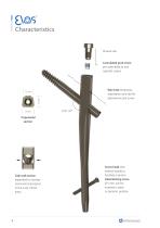
Cannulated grub screw pre-assembled to lock cephalic screws Wire hole temporary stabilisation and site for optional second screw Trapezoidal section Side wall section expanded to increase mechanical resistance in the most critical areas Screw head with internal socket to facilitate insertion Distal locking screw Ø 5 mm, can be inserted in static or dynamic position
Open the catalog to page 4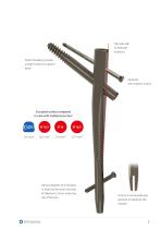
Flat side wall to facilitate insertion Flared threading creates a large surface to support bone Optional anti-rotation screws Occupied surface compared to nails with traditional section Various degrees of inclination in holes for the entry and exit of diaphysis screws, reducing risk of fracture Distal cut and lengthwise grooves to elasticize the implan
Open the catalog to page 5
Specific implants Cannulated cephalic screw Ø 5 mm Distal screw Ø 5 mm Anti-rotation scre
Open the catalog to page 6
This surgical technique is made available to healthcare professionals to illustrate the recommended procedures for using the Elos System. It offers general guide lines that should be followed with the awareness that the surgeon must consider the specific needs of each patient. The supervision of an experienced surgeon in the use of the Elos System is recommended. Patient positioning The patient is placed on the fracture table, in a supine or lateral decubitus position according to surgeon preference and/or fracture pattern. Reduction of the fracture is required, as anatomically as possible; the...
Open the catalog to page 7
1. Identify entrance point on the anterior third and posterior two-thirds of the greater trochanter. Position on the apex of the trochanter. 2. Open the medullary canal using the curved cannulated trocar (SE202) Use the mandrel (SE201) to insert the 0 2.8 mm guide wire. 3. Use the paratissue cannula (SE203) to prepare the nail site with the trochanteric cutter (SE204). Insert up to the line. 4. Assemble the nail on the introducer (SE206A) using the nail introducer rod (SE206B) and tighten using the assembler screwdriver (SE205). 5. Insert the nail on the guide wire and continue until the correct...
Open the catalog to page 8
7. Assemble the cannulated trocar (SE211) and cutter cannula (SE210) and insert into the hole at 127° on the guide until the lateral cortex is contacted. Insert the Ø 3 mm threaded guide wire. 8. Use the measure (SE212) to measure the length of the cephalic screw on the wire. If the guide wire is inserted up to the subchondral tissue, subtract 10 mm from the measured length. 9. If necessary, insert Ø 3 mm L. 350 mm anti-rotation wire using the cannula (SE214).
Open the catalog to page 9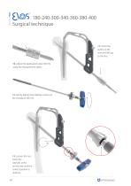
11. Insert the cutter on the wire and drill up to the line. 10. Adjust the graduated cutter (SE213) using the measurement taken. 12. Gently tighten the cephalic screws on the introducer (SE215). 13. Loosen the nut. Insert the cephalic screw on the wire until the correct position is reached.
Open the catalog to page 10
14. To retrieve the fragment, insert the compression pin (SE216) into the guide hole. Rotate the nut until the necessary compression is achieved. If necessary use the compression rod (SE235) into the holes of nut. 15. To stop rotation and slippage of the cephalic screw, fully tighten the locking grub screws pre-assembled on the nail, using the Flexible Screwdriver (SE217M). To allow slippage of the cephalic screw, unscrew one-quarter turn the locking grub screw preassembled, keeping the introduction sleeve in the horizontal or vertical position in relation to the operating table.
Open the catalog to page 11
180-240-300-340-360-380-400 Surgical technique ANTI-ROTATION SCREW OPTION 16. Use the measure (SE225) to measure the length of the screw on the wire. Alternatively, select a screw 15mm shorter than the cephalic screw used. Remove the wire. 17. Insert the protection cannula (SE218) and the trocar (SE219) and make a hole of 3 - 4 cm with the drill bit (SE220). 18. Insert the screw using the introducer (SE221) after assembling it as in point 21.
Open the catalog to page 12
19. Insert the cannula (SE218) and the measuring trocar (SE219) into the desired guide position, static or dynamic. Insert until the diaphysis is contacted. To achieve the correct position, the notch on the cannula must be visible as in the illustration. . \\.y-\ v‘ 20. Make a hole and measure using the notch on 21. Gently tighten the diaphyseal screws on the introducer (SE221). 22. Insert the diaphyseal screw with the introducer (SE221), until the reference mark (A). 23. Insert the cap, using a guide wire if necessary. Tighten with the 7mm Assembly Elex Screwdriver (SE205).
Open the catalog to page 13
300 - Technique for insertion of distal screws with guide 2. Insert the cannula (SE218) and the measuring trocar (SE219) into the desired hole of the guide. 3. Drill and measure the hole using the notch on the helical drill bit (SE220). 4. Insert the screw using the introducer (SE221) after assembling it as in point 21, and tighten until the reference mark (A). Repeat the operation for the other hole as necessary. 5. Insert the closure cap, using a guide wire if necessary. Tighten with the 7mm Assembly Hex Screwdriver (SE205).
Open the catalog to page 14All Intrauma catalogs and technical brochures
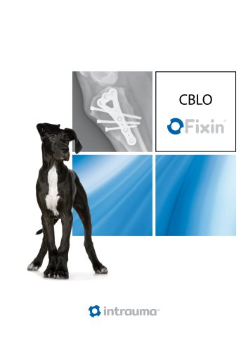 CBLO
CBLO4 Pages
 TPLO
TPLO16 Pages
 DPO
DPO8 Pages
 MicroCatalog
8 Pages
 FixinCatalog
44 Pages
 ISOLOCK
12 Pages
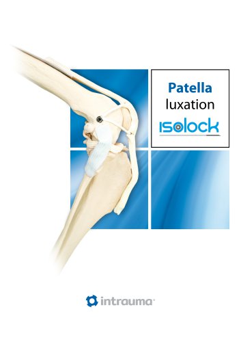 ISOLOCKPatellaProcedure
12 Pages
 Isolock CrCL Procedure
8 Pages
 Elafix
16 Pages
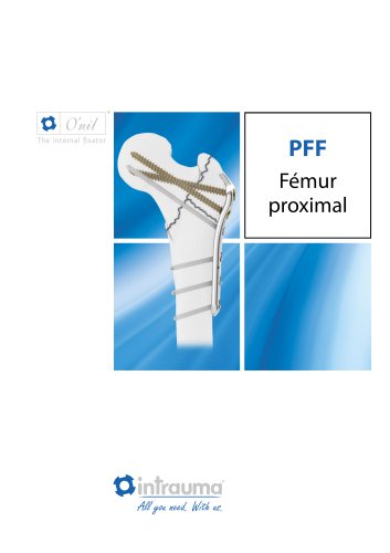 PFF
PFF8 Pages
 Anteversa
12 Pages
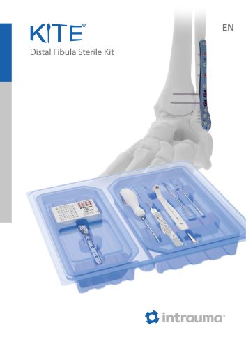
 KITE
KITE8 Pages
- Bone plate
- Compression plate
- Metallic compression plate
- Locking compression plate
- Distal compression plate
- Orthopedic surgery instrument kit
- Proximal compression plate
- Forearm compression plate
- Lateral compression plate
- Medial compression plate
- Humerus compression plate
- Radius compression plate
- Sterile instrument kit
- Femur compression plate
- Veterinary instrument kit
- Single-use instrument kit
- Veterinary bone compression plate
- Compression veterinary orthopedic screw
- Cortical bone veterinary orthopedic screw