ACLS

ACLS
The Anterior Clavicle Locking Plates System is designed for clavicle fractures, offering flexibility in screw placement. The system features anatomically pre-contoured plates with pre-angled holes for optimal fixation, particularly in the lateral clavicle area. The plates are made of titanium, and the screws are composed of TiAl6V4 ELI, providing improved fatigue strength and reduced risk of inflammation.
Specifications
The system includes various screws and drills, such as 3.5mm cortical screws and 2.7mm cortical screws, with options for locking and non-locking mechanisms. The plates are available in different configurations, including medial and lateral versions, with staggered and pre-angled holes for enhanced fixation.
Pre-operative Planning
Pre-operative planning involves selecting the appropriate plate and screw configuration based on the fracture type. Indications for use include meta- and diaphyseal clavicle fractures, non-unions, and corrective osteotomies. Contraindications include existing infections and lack of patient compliance.
Surgical Technique
Pre-operative preparation involves positioning the patient at a semi-sitting angle. The surgical approach can be transverse or anterosuperior, with careful incision placement to avoid direct suture over the plate. Plate insertion is performed from lateral to medial, with temporary fixation and fluoroscopic confirmation. Screw placement involves using specific drill guides and screwdrivers, with attention to avoid injuries to the subclavian artery and brachial plexus.
Postoperative Treatment
Postoperative care includes shoulder-arm dressing until wound healing and physical therapy. Full exertion is recommended after 5-7 weeks of fracture healing. Implant removal can be considered after 1.5 years or upon radiographic confirmation of healing.
Additional Information
The Dotize® anodization process enhances the titanium surface, reducing cold welding and increasing fatigue resistance. The locking mechanism allows for multi-directional screw placement without pre-threading, reducing debris and allowing screw re-setting up to three times.
Order Information
The document provides a comprehensive list of available plates, screws, and accessories, including order numbers and optional sterile packaging. For detailed cleaning and sterilization instructions, refer to the package insert.
Catalog excerpts

Implants trauma Anterior Clavicle Locking Plates System
Open the catalog to page 1
CAUTION: Federal Law (USA) restricts this device to sale by or on the order of a board certified physician. WARNING: If there is no sufficient bone healing, wrong or incomplete postoperative care, plate might break. All ITS plates are preformed anatomically as a matter of principle. If adjustment of the plate to the shape of the bone is required, this is possible by carefully bending gently in one direction once. Particular care is required when bending in the region of a plate hole, as deformation of the plate may lead to a failure of the locking mechanism. The plate must not be buckled or bent...
Open the catalog to page 2
1. Introduction P. 5 Preface P. 6 Screws P. 7 Properties P. 8 Pre-operative planning P. 8 Indications P. 9 Contraindications P. 9 Time of operation 2. Surgical Technique P. 10 Pre-operative patient preparation P. 11 Access P. 11 Exposure P. 12 Reduction P. 12 Plate insertion P. 13 Placement of the 0 2.7/3.0mm screws P. 14 Placement of the 0 3.5mm screws P. 16 Postoperative treatment P. 16 Explantation 3. Information P. 17 Locking P. 17 Dotize® P. 18 Order list
Open the catalog to page 3
Preface The Locking Anterior Clavicle Plate System is a proven osteosynthesis system for various clavicle fractures. The special feature of this implant is the free choice of screw placement. The user is able to set any desired screw in any hole (either locking or non-locking screw). In particular the anatomical plate design as well as the pre-angled plate holes of the lateral plate version provide an optimal fixation in the very lateral area of the clavicle.
Open the catalog to page 5
Cortical Screw, Locking, D=3.5mm, SH Spiral Drill D=2.7mm, L=100mm, AO Connector Screwdriver, WS 2.5, self-holding sleeve Spiral Drill D=2.7mm, L=100mm, AO Connector Screwdriver, WS 2.5, self-holding sleeve Cortical Screw, D=2.7mm Spiral Drill D=2.0mm, L=100mm, AO Connector Screwdriver, Torque, T9x70 Cancellous Stabilization Screw, D=3.0mm, RH Spiral Drill D=2.0mm, L=100mm, AO Connector Screwdriver, Torque, T9x70
Open the catalog to page 6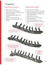
Properties Properties of the material: • Plate material: Titanium • Material of screws: TiAl6V4 ELI • Easier removal of the implant after the fracture has healed • Improved fatigue strength of the implant • Reduced risk of cold welding • Reduced risk of inflammation and allergy • Multi-directional Locking • Anatomical pre-contoured plate design • Anterior plate position minimizes the risk of injuries of the subclavian artery and lung perforation • Medial and lateral version • 3.5mm cortical screws in the shaft (optionally locking) • 2.7mm cortical screws and 3.0mm locking cancellous screws in...
Open the catalog to page 7
Pre-operative planning Meta- and diaphyseal clavicle fractures Far lateral clavicle fractures Open and closed fractures Non-unions Mal-unions Corrective os
Open the catalog to page 8
Contraindications: ♦ Existing infections in the fracture zone and operation area ♦ Common situations that do not allow osteosynthesis ♦ Obesity ♦ Lack of patient compliance Time of operation: ♦ Immediately after trauma or delayed ♦ After regression of swelling
Open the catalog to page 9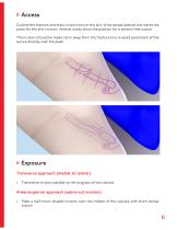
Access Outline the fracture and draw incision line on the skin. A horizontal dashed line marks the place for the skin incision. Vertical marks show the position for a tension free suture. The incision should be made 1-2cm away from the fracture line to avoid placement of the suture directly over the plate. Exposure Transverse approach (medial to lateral) • Transverse incision parallel to the long axis of the clavicle. Anterosuperior approach (sabre-cut incision) • Make a half-moon shaped incision over the middle of the clavicle with short dorsal branch
Open the catalog to page 11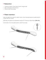
Reduction • Temporary fixation of the fracture parts using forceps • Seek compression of the fracture • Control under fluoroscopy Plate insertion Insert the plate from lateral to medial under a bone holding forceps and additionally fix in place with two clamps. Optionally, the plate can be stabilized using the ITS. Temporary Plate Holder (58164-150). Confirmation of correct plate position under fluoroscopy.
Open the catalog to page 12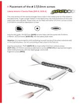
Placement of the Ø 2.7/3.0mm screws Lateral Anterior Clavicle Plate (21119-X; 21120-X) The cross section of the clavicle changes from a tube in the medial area to a flat ellipse in the lateral area. To gain proper fixation in the lateral area, the hole dimension of the outer plate holes were adjusted. These holes can be filled with either D=2.7mm cortical screws or D=3.0mm cancellous stabilization screws. Use the drill guide, D=2.0/2.7mm (62202) to bore holes with the spiral drill D=2.0mm, L=100mm, AO Connector (61203-100) into the lateral plate holes. Attention: It is recommend to drill oscillating,...
Open the catalog to page 13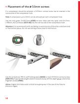
Placement of the Ø 3.5mm screws If a compression should be achieved, a D=3.5mm cortical screw has to inserted in the narrow area of the compression hole. Note: A compression up to 3.5mm can be achieved per each compression hole. Use the drill guide, D=2.0/2.7mm (62202) to bore holes with the spiral drill D=2.7mm, L=100mm, AO Connector (61273-100) into the narrow area of the compression hole. Attention: It is recommend to drill oscillating, to avoid injuries of the artery subclavia and/ or the brachial plexus. Do not use locking screws close to the fracture. Use the screwdriver, WS 2.5, self-holding...
Open the catalog to page 14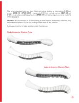
The remaining plate holes are then filled, with either locking or non-locking D=3.5mm screws (32351-XX / 37351-XX-N) respectively D=2.7mm cortical screws (32271-XX) or D=3.0mm cancellous stabilization screws (37303-XX) at the lateral plate versions - suitable drills see page 6. Attention: It is recommend to drill oscillating, to avoid injuries of the artery subclavia and/ or the brachial plexus. Do not use locking screws close to the fracture. Subsequent control of plate position under fluoroscopy. Medial Anterior Clavicle Plate Lateral Anterior Clavicle Plate
Open the catalog to page 15
Postoperative treatment • Shoulder-arm dressing until wound healing (approx. 2 weeks) • Physical therapy • Full exertion after fracture healing (approx. 5-7 weeks) Explantation If desired by the patient, the implant can be removed. Removal should be performed at the earliest 1 1/2 years later or after radiographic verification of the healed bone. The problem of cold welding was resolved by using a special surface treatment (for further information see page 17).
Open the catalog to page 16All I.T.S. catalogs and technical brochures
 CTN - Cannulated Tibia Nail
28 Pages
 ufs
ufs1 Page
 DHL
DHL2 Pages
 ITS
ITS2 Pages
 SCL
SCL32 Pages
 SLS
SLS24 Pages
 OL - Olecranon Locking Plate
24 Pages
 PHL
PHL24 Pages
 PHLs
PHLs20 Pages
 CLS
CLS28 Pages
 CFN
CFN32 Pages
 OLS
OLS24 Pages
 SR Sacral Rods
20 Pages
 HCS
HCS24 Pages
 TOS Twist-Off Screw
20 Pages
 TLS
TLS20 Pages
 PRS-RX
32 Pages
 HLS
HLS20 Pages
 ES
ES20 Pages
 SR
SR20 Pages
 FL
FL24 Pages
 PL - Pilon Locking Plate small
12 Pages
 FLS
FLS24 Pages
 PFL
PFL20 Pages
 DTL
DTL24 Pages
 HTO
HTO24 Pages
 PTL
PTL32 Pages
 DFL
DFL32 Pages
 CAS
CAS40 Pages
 FCN
FCN20 Pages
 HOL
HOL24 Pages
 CAL
CAL20 Pages
 DUL
DUL24 Pages


Archived catalogs


- Bone plate
- Compression plate
- Metallic compression plate
- Locking compression plate
- Distal compression plate
- Compression bone screw
- Metallic compression bone screw
- Proximal compression plate
- Arthrodesis nail
- Forearm compression plate
- Lateral compression plate
- Medial compression plate
- General purpose compression bone screw
- Tibia compression plate
- Metallic intramedullary nail
- Humerus compression plate
- Cannulated compression bone screw
- Radius compression plate
- Proximal fixation intramedullary nail
- Arthrodesis plate