CFN
1 /32Pages

CFN
1 /32Pages
Catalog excerpts

Implants trauma Cannulated Femur Nail
Open the catalog to page 1
CAUTION: Federal Law (USA) restricts this device to sale by or on the order of a board certified physician. WARNING: If there is no sufficient bone healing, wrong or incomplete postoperative care, implant might break.
Open the catalog to page 2
1. Introduction P. 5 Preface P. 6 Screws P. 6 Properties P. 7 Pre-operative measurement of nail Length P. 8 Indications & Contraindications 2. Surgical Technique P. 10 Pre-operative patient planning P. 10 Incision P. 11 Assembly of the insertion guide P. 12 Locating entry portal P. 12 Nailing P. 13 Proximal Locking / Femoral Neck P. 14 Proximal Locking / Greater to lesser trochanter P. 15 Measuring of proximal screw length P. 16 Distal Locking P. 17 Measuring of distal screw length P. 18 Removal of the insertion guide P. 18 Endcap insertion P. 20 Postoperative treatment P. 20 Na il removal 3....
Open the catalog to page 3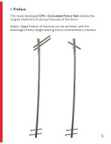
Preface The newly developed CFN - Cannulated Femur Nail enables the surgical treatment of various fractures of the femur. Stable, ridged fixation of fractures can be achieved, with the advantage of early weight bearing due to intramedullary insertion.
Open the catalog to page 5
32652-xxx Cortical Screw, D=6.5mm 61502-350 Spiral Drill, D=5.0mm, L=350mm, AO Connector 54353-230SH Screwdriver Shank, PRS, Solid, WS 3.5mm, L=230mm, AO Connector 32475-xx Cortical Screw, D=4.7mm 61427-140 Spiral Drill, Angledrived, D=4.2mm, L=140mm 54353-230SH Screwdriver Shank, PRS, Solid, WS 3.5mm, L=230mm, AO Connector o Properties Properties of the material: ♦ Nail material: TiAl6V4 ELI ♦ Material of screw: TiAl6V4 ELI ♦ Easier removal of the implant is necessary ♦ Improved fatigue strength of the implant ♦ Reduced risk of cold welding ♦ Reduced risk of inflammation and allergy Properties...
Open the catalog to page 6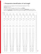
Preoperative identification of nail length 1. Determine the nail length with the template (see right) and a X-Ray Attention: Scale 1.6:1 2. Determine the nail length with the X-Ray ruler (59203). 3. Insert the calibrated D=3.0mm guide wire with ball tip (35301-800) or the D=2.5mm guide wire (35251-800) and read off the required nail length at the calibrated guide wire. Scale 1.6:1
Open the catalog to page 7
Indications: ♦ Open and closed metaphyseal and diaphyseal fractures ♦ Subtrochanteric and supracondylar fractures ♦ Segmental fractures ♦ Non-unions, mal-unions and delayed union fractures ♦ Pathological fractures, impending pathological fractures and tumor resections ♦ Fractures proximal to a total knee arthroplasty Contraindications: ♦ Active infection ♦ Skeletally immature patients ♦ Severe osteoporosis or inadequate bone stock ♦ Skin and soft tissue problems ♦ Foreign body (material) sensitivity ♦ Obesity ♦ Lack of patient compliance
Open the catalog to page 8
Surgical Technique
Open the catalog to page 9
o Incision ♦ Incision 2 - 3cm proximal to the greater trochanter in line with the longitudinal axis of the femur. ♦ Longitudinally split the fascia and use a trochar or finger palpation to identify the greater trochanter.
Open the catalog to page 10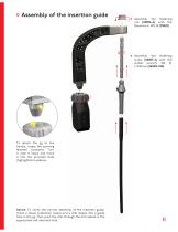
o Assembly of the insertion guide tm- Assembly the fastening nut (118006-4) with the flatwrench, WS 20 (70020) Assembly the fastening screw (118007-4) with the socket wrench, WS 10, L=250mm (561002-250) To attach the jig to the handle, rotate the spinning fastener clockwise. Turn it until it stops and move it into the provided slots (highlighted in yellow). Advice: To verify the correct assembly of the insertion guide, insert a tissue protection sleeve and a drill sleeve into a guide hole in the jig. Then push the drill through the drill sleeve in the appropriate nail interlock hole.
Open the catalog to page 11
• Identification of the insertion portal is extremely important. The drill tip, guide wire or awl should be inserted at the medial edge of the greater trochanter on the AP fluoroscopic view and in line with the longitudinal axis of the femur on the lateral fluoroscopic view. • Open the proximal medullary canal with the required drill, awl or gimlet to the desired diameter with the appropriate soft tissue protector in place. • Introduce the D=3.0mm guide wire with ball tip (35301-800) when using the optional available reamer down to the level of the fracture, reduce the fracture and pass the guide...
Open the catalog to page 12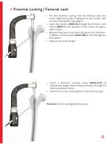
Proximal Locking / Femoral neck • For the proximal Locking into the femoral neck the screw alignment guide is attached to the handle with the spinning fastener (see page 11). • Insert the trochar (118007-8) through the D=5.1mm drill sleeve (118007-7) and advance to the cortex through a stab incision. • Remove the trochar and insert the spiral drill, D=5.0mm, L=350mm, AO Connector (61502-350) to drill through the drill sleeve. • Measure the screw length. • Insert a D=6.5mm cortical screw (32652-XXX) of appropriate length determined previously through the tissue protection sleeve. • Verify the...
Open the catalog to page 13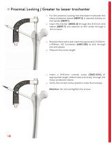
Proximal Locking / Greater to lesser trochanter • For the proximal Locking into the lesser trochanter the tissue protection sleeve (118007-5) is inserted directly on the handle (118007-1) • Insert the trochar (118003-12) through the D=5.1mm drill sleeve (118007-7) and advance to the cortex through a skin incision. • Remove the trochar and insert the spiral drill, D=5.0mm, L=350mm, AO Connector (61502-350) to drill through the drill sleeve. • Measure the screw length. • Insert a D=6.5mm cortical screw (32652-XXX) of appropriate length determined previously through the tissue protection sleeve....
Open the catalog to page 14
Measuring of proximal screw length Drill the screw holes under fluoroscopy, then read off the required screw length at the end of the calibrated D=5.0mm spiral drill (61502-350).
Open the catalog to page 15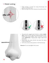
Distal Locking • Distal locking is carried out using fluoroscopy and perfect circle technique. • Before locking, the correct reduction should be verified. • The spiral drill, angledrived, D=4.2mm, L=140mm (61427140) is used to drill through the medial and lateral cortex. Measure the screw length. Insert a D=4.7mm cortical screw (32475-XX) of appropriate length determined previously. • Additionally the screw should rise above the lateral cortex at least 2mm • Verify the correct screw position in the fluoroscopy. Attention: Do not overtighten the scre
Open the catalog to page 16All I.T.S. catalogs and technical brochures
 CTN - Cannulated Tibia Nail
28 Pages
 ufs
ufs1 Page
 DHL
DHL2 Pages
 ITS
ITS2 Pages
 SCL
SCL32 Pages
 SLS
SLS24 Pages
 OL - Olecranon Locking Plate
24 Pages
 PHL
PHL24 Pages
 PHLs
PHLs20 Pages
 CLS
CLS28 Pages
 ACLS
ACLS20 Pages
 OLS
OLS24 Pages
 SR Sacral Rods
20 Pages
 HCS
HCS24 Pages
 TOS Twist-Off Screw
20 Pages
 TLS
TLS20 Pages
 PRS-RX
32 Pages
 HLS
HLS20 Pages
 ES
ES20 Pages
 SR
SR20 Pages
 FL
FL24 Pages
 PL - Pilon Locking Plate small
12 Pages
 FLS
FLS24 Pages
 PFL
PFL20 Pages
 DTL
DTL24 Pages
 HTO
HTO24 Pages
 PTL
PTL32 Pages
 DFL
DFL32 Pages
 CAS
CAS40 Pages
 FCN
FCN20 Pages
 HOL
HOL24 Pages
 CAL
CAL20 Pages
 DUL
DUL24 Pages


Archived catalogs


- Bone plate
- Compression plate
- Metallic compression plate
- Locking compression plate
- Distal compression plate
- Compression bone screw
- Metallic compression bone screw
- Proximal compression plate
- Arthrodesis nail
- Forearm compression plate
- Lateral compression plate
- Medial compression plate
- Tibia compression plate
- General purpose compression bone screw
- Metallic intramedullary nail
- Humerus compression plate
- Cannulated compression bone screw
- Radius compression plate
- Arthrodesis plate
- Proximal fixation intramedullary nail