DUL

DUL
The Distal Ulna Locking Plate is a titanium implant system designed for stabilizing distal ulna fractures. It features locking screws that conform to the bone's contour, enhancing stability and reducing inflammation risk.
Specifications
The plate comes in various sizes (3, 4, 6-hole) and configurations (left/right, wide/small). It includes multi-directional locking and K-Wire holes for preliminary fixation. The screws are made from TiAl6V4 ELI, known for strength and compatibility.
Indications & Contraindications
Indications include fractures of the ulnar head and multifragmentary fractures. Contraindications include existing infections, osteoporosis, obesity, and lack of patient compliance.
Surgical Technique
The procedure involves positioning the patient supine, making a precise incision, and exposing the fracture area. The plate is inserted and secured with screws for optimal alignment and stability. Postoperative care includes a dorsal splint and potential physiotherapy.
Postoperative Treatment & Explantation
A dorsal splint is recommended for 1-2 weeks post-surgery. The implant can be removed after bone healing, typically one and a half years later.
Material Properties
The titanium plate and screws reduce the risk of cold welding and inflammation. Dotize® anodization enhances surface wear resistance and reduces allergic reactions.
Sterilization Guidelines
Implants are supplied non-sterile and require steam sterilization before use. Care should be taken to avoid surface damage during cleaning.
Warnings
Implants should be used once and handled carefully to prevent damage. Regular follow-up examinations are advised, and implants from different manufacturers should not be combined.
- Recommended equipment includes an alkaline cleaning agent (pH < 11), nylon brushes, and running water.
- Steps: Dismantle instruments, rinse surface dirt, apply cleaning agent with a brush, and rinse thoroughly for at least 1 minute.
- Use authorized disinfectants according to manufacturer instructions. Automatic cleaning may include a final rinse at 90°C for 5 minutes for thermal disinfection.
- Drying temperature should not exceed 110°C.
- Inspect instruments for dirt, lubricate movable parts, and ensure proper assembly and function.
- Hospital is responsible for assembly, inspection, and packaging. Instruments should be dismantled for sterilization, preferably using heat/steam.
- Follow manufacturer’s recommendations and do not exceed appliance capacity.
- Cycle parameters: Prevacuum at 132°C for 4 minutes or 134°C for 18 minutes.
- Follow hospital guidelines for disposal.
- Patients should be informed about post-implantation behavior and the importance of reporting any negative changes.
- Instruments must be cleaned, disinfected, inspected, and sterilized before returning to ITS GmbH.
- Instructions are validated for re-use suitability. Reconditioners must ensure effective preparation and validate processes.
- Includes symbols for prescription, single use, expiry date, sterilization methods, and more.
Catalog excerpts

Implants trauma Distal Ulna Locking Plate
Open the catalog to page 1
CAUTION: Federal Law (USA) restricts this device to sale by or on the order of a board certified physician. WARNING: If there is no sufficient bone healing, wrong or incomplete postoperative care, plate might break.
Open the catalog to page 2
1. Introduction P. 5 Preface P. 6 Screws P. 7 Properties P. 8 Indications & Contraindications P. 8 Time of operation 2. Surgical Technique P. 10 Positioning of the patient P. 10 Exposure P. 11 Plate insertion P. 12 Placement of the screws P. 15 Postoperative treatment P. 15 Explantation P. 15 Summary 3. Information P. 17 Locking P. 17 Dotize® P. 18 Order list P. 20 Sterilization guidelines P. 22 Notes
Open the catalog to page 3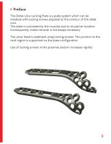
Preface The Distal Ulna Locking Plate is a plate system which can be installed with locking screws adjusted to the contour of the distal ulna. The plate is concealed by the muscles due to its palmar location. Consequently, metal removal is not always necessary. The ulnar head is stabilized using locking screws. The junction to the neck region is supported via the plate configuration. Use of locking screws in the proximal section increases rigidity.
Open the catalog to page 5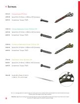
Spiral Drill, D=2.0mm, L=100mm, AO Connector Cortical Stabilization Screw, D=3.0mm, RH Spiral Drill, D=2.4mm, L=100mm, AO Connector Cancellous Stabilization Screw, D=3.0mm, RH Spiral Drill, D=2.0mm, L=100mm, AO Connector Spiral Drill, D=1.8mm, L=100mm, AO Connector Guide Wire, Steel, D=1.6mm, L=150mm, TR, with thread All I.T.S. locking plates are anatomically pre-contoured. In the unlikely event that the plate has to be formed to the bone please notice that slight contouring is possible. Attention: Significant bending at the locking holes will reduce locking effectiveness and if bend more than...
Open the catalog to page 6
Properties Properties of the material: • Plate material: Titanium • Material of screws: TiAl6V4 ELI • Easier removal of implant after fracture has healed • Improved fatigue strength of implant • Reduced risk of cold welding • Reduced risk of inflammation and allergy Multi-directional locking Anatomically plate design Version left/right Version wide/small K-Wire holes for preliminary plate fixation 5 distal plate holes for optimal reconstruction of the distal radio-ulnar joint (DRUJ) Long hole for optimal positioning and adjustment of ulna length Pointed proximal plate end for percutaneous insertion...
Open the catalog to page 7
Indications, Contraindications & Time of operation Indications: • • • • • Fractures of the ulnar head Multifragmentary fractures of the ulnar head Subcapital fractures of the ulnar head Metaphyseal comminuted fractures of the distal ulna Combined ulnar head and ulnar shaft fractures Existing infections in the fracture zone and operation area Common situations that do not allow osteosynthesis (osteoporosis) Obesity Lack of patient compliance Time of operation: • Immediately after trauma or delayed • After regression of swelling
Open the catalog to page 8
Surgical Technique
Open the catalog to page 9
Positioning of the patient • The patient is placed in the supine position with pneumatic deprivation of blood supply • The hand is positioned on a x-ray transparent surgical hand table Exposure • The skin incision is made approx. 5mm to the palmar side of the mid lateral line from the tip of the ulna head handle to 5-7cm proximally. • After sectioning of the skin and the subcutis, outline the superficial branch and the ulnar nerve in the distal region. • Sharply separate the pronator quadratus muscle on the ulnar side and hold subperiostally medially. • The fracture area is outlined and exposed...
Open the catalog to page 10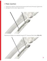
Plate insertion • Temporarily reduction of the fractured sections with the aid of forceps or guide wires • Subsequent control under image convertor Optionally, the plate can be stabilised using the ITS. Temporary Plate Holder (58164-150).
Open the catalog to page 11
Placement of the screws With the spiral drill, D=2.0mm, L=100mm, AO Connector (61203-100), drill through the drill guide, D=2.0/2.4mm (62215) into the long-hole. Determine appropriate length using the depth gauge, PROlock II (59026). Insert the D=2.7mm cortical screw (32271-XX) with the screwdriver, Torque, T9x70 (5609570). Advice: For optimal alignment of the plate with ulna length, we recommend to first occupy the longhole.
Open the catalog to page 12
Then insert a D=2.4mm stabilization screw, RH (37241-XX) or a D=3.0mm cancellous stabilization screw, RH (37303-XX) with the screwdriver, Torque, T9x70 (56095-70) into a distal plate hole. (Spiral drill, D=1.8mm, L=100mm, AO Connector (61183-100) for D=2.4mm stabilization screw / spiral drill, D=2.0mm, L=100mm, AO Connector (61203-100) for D=3.0mm cancellous stabilization screw) Use the screwdriver, Torque, T9x70 (56095-70) to insert a D=3.0mm cortical stabilization screw, RH (37304-XX) of appropriate lengths determined previously with the depth gauge, PROlock II (59026) into a shaft plate hole....
Open the catalog to page 13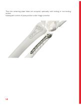
Then the remaining plate holes are occupied, optionally with locking or non-locking screws. Subsequent control of plate position under image converter.
Open the catalog to page 14
Postoperative treatment • Dorsal splint (1-2 weeks) • With mobilisation stability: physiotherapy possible in the immediate postoperative period Explantation If desired by the patient, the implant can be removed. Removal should be performed at the earliest one and a half years later or after radiographic verification of the healed bone. The problem of cold welding was solved by using a special treatment (for further information see page 17). Summary The ITS. Distal Ulna Locking Plate is proven in the osteosynthesis of the most diverse of fractures of the distal ulna. This technique attains anatomical...
Open the catalog to page 15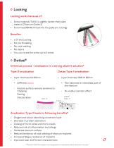
Locking Locking works because of: • Screw material (TiAlV) is slightly harder than plate material (Titanium Grade 2) • Screw head forms thread into the plate (no cutting) ± 15° and Locking No pre threading No cold welding No debris You can re-set the screw up to 3 times Dotize® Chemical process - anodization in a strong alkaline solution* Type III anodization Dotize Type II anodization + Film becomes an interstitial part of the titanium - Implant surface remains sensitive to: Chipping Peeling Discoloration Type - III - No visible cosmetic effect Dotize® Type - II Ti-Oxid Anodization Type II leads...
Open the catalog to page 17All I.T.S. catalogs and technical brochures
 CTN - Cannulated Tibia Nail
28 Pages
 ufs
ufs1 Page
 DHL
DHL2 Pages
 ITS
ITS2 Pages
 SCL
SCL32 Pages
 SLS
SLS24 Pages
 OL - Olecranon Locking Plate
24 Pages
 PHL
PHL24 Pages
 PHLs
PHLs20 Pages
 CLS
CLS28 Pages
 ACLS
ACLS20 Pages
 CFN
CFN32 Pages
 OLS
OLS24 Pages
 SR Sacral Rods
20 Pages
 HCS
HCS24 Pages
 TOS Twist-Off Screw
20 Pages
 TLS
TLS20 Pages
 PRS-RX
32 Pages
 HLS
HLS20 Pages
 ES
ES20 Pages
 SR
SR20 Pages
 FL
FL24 Pages
 PL - Pilon Locking Plate small
12 Pages
 FLS
FLS24 Pages
 PFL
PFL20 Pages
 DTL
DTL24 Pages
 HTO
HTO24 Pages
 PTL
PTL32 Pages
 DFL
DFL32 Pages
 CAS
CAS40 Pages
 FCN
FCN20 Pages
 HOL
HOL24 Pages
 CAL
CAL20 Pages


Archived catalogs


- Bone plate
- Compression plate
- Metallic compression plate
- Locking compression plate
- Distal compression plate
- Compression bone screw
- Metallic compression bone screw
- Proximal compression plate
- Arthrodesis nail
- Forearm compression plate
- Lateral compression plate
- Medial compression plate
- General purpose compression bone screw
- Tibia compression plate
- Metallic intramedullary nail
- Humerus compression plate
- Cannulated compression bone screw
- Radius compression plate
- Proximal fixation intramedullary nail
- Arthrodesis plate