ES

ES
The Epiphysis Screw by ITS is designed for treating Slipped Capital Femoral Epiphysis (SCFE) in young individuals. It provides stabilization with minimal invasiveness, reducing joint perforation risks. The screw stabilizes the femoral head's epiphysis and acts as a tension screw without joint perforation. Its large head prevents embedding in bone and allows for percutaneous removal.
Made from TiAl6V4 ELI, the screw offers easy removal post-healing, increased fatigue strength, and reduced inflammation risk. It features a cannulated cancellous tension screw with a 10mm thread, a core diameter of 5mm, and an outer diameter of 6.5mm. Lengths range from 50 to 120mm in 5mm increments. It is self-drilling, self-tapping, and has a large screw head for easy removal.
Indications include acute and chronic epiphysis loosening and femoral head fractures in children. Contraindications include septic joint inflammation, existing infections, and lack of patient compliance.
SCFE involves femoral head slippage, leading to complications like avascular necrosis. Surgical stabilization is preferred without repositioning. The procedure involves using Kirschner’s wire and image intensifiers for precise screw placement. The screw should not perforate the joint and must be retightened due to growth.
Dotize®: Anodization improves implant surface properties, reducing inflammation risk and increasing fatigue resistance. Order List: Details various screw sizes and associated tools. Reconditioning Manual: Provides guidelines for cleaning and sterilizing non-sterile implants and reusable instruments.
Automatic cleaning is preferred due to higher efficacy. Manual cleaning should only be used if automatic processes are unavailable. Recommended equipment includes a pH 9-11 cleaning agent, nylon brushes, and running water. Instruments should be soaked in a cleaning agent/disinfectant solution, followed by ultrasound treatment for 5 minutes and a 15-minute soak. Rinse thoroughly with tap water and dry immediately.
If a cleaning agent without disinfectant properties is used, separate disinfection is required.
Inspect each instrument for visible dirt and repeat cleaning if necessary. Lubricate movable mechanisms and check the mobility of parts. Ensure instruments can be easily reassembled.
Packaging is for transport only and not suitable for sterilization. Sterilization should be done using the fractionated pre-vacuum procedure according to EN 285 or EN 13060 and EN ISO 17665. Recommended steam sterilization parameters are 134°C for 5 to 18 minutes.
Hospital guidelines apply for disposal. Instruments returned to I.T.S. GmbH must be cleaned, disinfected, inspected, and sterilized, accompanied by a decontamination confirmation.
Instructions have been validated for reconditioning medical devices. Reconditioners must ensure the process achieves desired results through validation and routine inspections.
Patients should be informed about post-implantation behavior and the importance of reporting changes or accidents affecting the implant.
Symbols include prescription, single use, expiry date, sterilization methods, and more. Contact I.T.S. GmbH for further information.
Catalog excerpts
Implants trauma Epiphysis Screw
Open the catalog to page 1
1. Introduction P. 5 Preface P. 6 Properties P. 7 Indications & Contraindications P. 8 Slipped Capital Femoral Epiphysis (SCFE) 2. Surgical Technique P. 8 Preparation of operation P. 9 Preparation P. 9 Surgical Technique P. 13 Attaching the screw on the other side P. 13 Explantation 3. Information P. 15 Dotize® P. 16 Order list P. 18 Reconditioning Manual
Open the catalog to page 3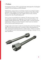
Preface The Epiphysis Screw of ITS. was especially developed for the Slipped Capital Femoral Epiphysis (SCFE) disease. Stabilization using screws is minimally invasive according to today‘s standard. With respect to the blood circulation of the neck of the femur, it is advantageous to use a single central screw, and this reduces the risk of a perforated joint. Such a screw must fulfill two conditions. On the one hand, it has to sufficiently stabilise the epiphysis of the head of the femur to enable at least partial stress. On the other hand, it should hold the epiphysis by means of a short thread...
Open the catalog to page 5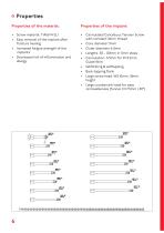
Properties Properties of the material: • Screw material: TiAl6V4 ELI • Easy removal of the implant after fracture healing • Increased fatigue strength of the implants • Decreased risk of inflammation and allergy • Cannulated Cancellous Tension Screw with constant 10mm thread • Core diameter 5mm • Outer diameter 6.5mm • Lengths: 50 - 120mm in 5mm steps • Cannulation: 3.5mm for D=3.2mm Guide Wire • Selfdrilling & selftapping • Back-tapping flank • Large screw head: WS 10mm, 10mm height • Large countersink head for easy removableness (funnel: D=7.5mm / 30°)
Open the catalog to page 6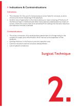
Indications & Contraindications Indications: • The indication for the use of a transcutaneous screw holds for all acute, acute to chronic and chronic loosening of the epiphysis. • Another area of application is the transcutaneous or open screwing of fractures of the femoral head in childhood and other transcutaneous stabilisations by means of screws, where the screws have to be prevented from setting into the bony tissue but percutaneous removal is allowed. Contraindications: • The screw connection of an epiphysiolysis (attachment of a foreign body) in the context of a septic joint inflammation...
Open the catalog to page 7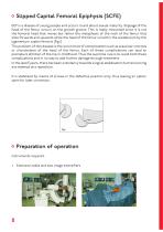
Slipped Capital Femoral Epiphysis (SCFE) ECF is a disease of young people and occurs round about sexual maturity. Slippage of the head of the femur occurs on the growth groove. This is really misnamed since it is not the femoral head that moves but rather the metaphysis of the neck of the femur that slips forwards and upwards while the head of the femur is held in the acetabulum by the ligamentum capitis femoris (Fig.1). The problem of this disease is the occurrence of complications such as avascular necrosis or chondrolysis of the head of the femur. Each of these complications can lead to premature...
Open the catalog to page 8
Preparation • The patient is placed on the extension table and two image intensifiers are arranged in such a way that the proximal end of the femur can be represented in two planes. • The image intensifiers have to be placed in such a way that the X-ray tubes can be positioned respectively above (A-P level) and between the legs (sagittal level) in order to protect the operating team from X-rays as best as possible. • The patient is placed on the extension table with carefully internally rotated leg (neutralising the femoral torsion). • Care must be taken not to force the internal rotation of...
Open the catalog to page 9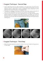
Surgical Technique - Second Step • Under observation from the image intensifiers in the lateral plane, the point at the centre of the neck of the femur in the A-P plane (where the Kirschner’s wire was attached earlier) is determined to allow an additional central attachment to the epiphysis of the head of the femur in the sagittal plane. • The greater the slippage of the head of the femur, the further ventral is the point of entry, and thus the steeper the Kirschner’s wire must be in the lateral plane. • Insertion of the Kirschner’s wire under observation from the image intensifiers (both planes)...
Open the catalog to page 10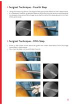
Surgical Technique - Fourth Step • Using the measuring device, the length of the appropriate hollow screw is determined. • It is necessary, however, to take the distance from the joint into account and therefore to choose a screw some 0.5cm longer since the Kirschner Wire stops about 1cm in front of the joint cavity. Surgical Technique - Fifth Step • Screw in the hollow screw above the guide wire under observation from the image intensifiers in both planes. • Care must be taken not to perforate the joint.
Open the catalog to page 11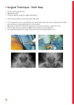
Surgical Technique - Sixth Step • Screw out the guide wire • Release the leg • Check mobility using the image intensifiers. • Care must be taken not to perforate the joint! • It is important not to countersink the bolt head into the bone, otherwise the easy percutaneous removeableness will not be able. • Because of the short screw thread you can use the screw as a „dynamic“ one. • This means that you should retighten the screw due to the growth. • For that the head of the screw must stick out from the bone 0.5 - 1cm.
Open the catalog to page 12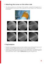
Attaching the screw on the other side • The same procedure as in the steps of the operation, except that the guide wire is inserted parallel to the Kirschner Wire fastened to the skin distal to the Tuberculum inominatum. Explantation • Removal of the epiphysis screw is carried out after closure of the grwoth groove and checked using the image intensifiers and is carried out percutaneously. • A guide wire starting from the scar of the screw attachment is introduced into the funnel shaped screw head of the epiphysis screw and the latter removed by means of the socket wrench, WS 10, L=250mm (561002-250)...
Open the catalog to page 13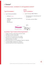
Dotize® Chemical process - anodization in a strong alkaline solution* Dotize Type II anodization • Layer thickness 2000-10 000nm + Film becomes an interstitial part of the titanium + Different colors - Implant surface remains sensitive to: Chipping Peeling Discoloration - No visible cosmetic effect Anodization Type II leads to following benefits* • • • • • • • • Oxygen and silicon absorbing conversion layer Decrease in protein adsorption Closing of micro pores and micro cracks Reduced risk of inflammation and allergy Hardened titanium surface Reduced tendency of cold welding of titanium implants...
Open the catalog to page 15All I.T.S. catalogs and technical brochures
 CTN - Cannulated Tibia Nail
28 Pages
 ufs
ufs1 Page
 DHL
DHL2 Pages
 ITS
ITS2 Pages
 SCL
SCL32 Pages
 SLS
SLS24 Pages
 OL - Olecranon Locking Plate
24 Pages
 PHL
PHL24 Pages
 PHLs
PHLs20 Pages
 CLS
CLS28 Pages
 ACLS
ACLS20 Pages
 CFN
CFN32 Pages
 OLS
OLS24 Pages
 SR Sacral Rods
20 Pages
 HCS
HCS24 Pages
 TOS Twist-Off Screw
20 Pages
 TLS
TLS20 Pages
 PRS-RX
32 Pages
 HLS
HLS20 Pages
 SR
SR20 Pages
 FL
FL24 Pages
 PL - Pilon Locking Plate small
12 Pages
 FLS
FLS24 Pages
 PFL
PFL20 Pages
 DTL
DTL24 Pages
 HTO
HTO24 Pages
 PTL
PTL32 Pages
 DFL
DFL32 Pages
 CAS
CAS40 Pages
 FCN
FCN20 Pages
 HOL
HOL24 Pages
 CAL
CAL20 Pages
 DUL
DUL24 Pages


Archived catalogs


- Bone plate
- Compression plate
- Metallic compression plate
- Locking compression plate
- Distal compression plate
- Compression bone screw
- Metallic compression bone screw
- Proximal compression plate
- Arthrodesis nail
- Forearm compression plate
- Lateral compression plate
- Medial compression plate
- General purpose compression bone screw
- Tibia compression plate
- Metallic intramedullary nail
- Humerus compression plate
- Cannulated compression bone screw
- Radius compression plate
- Proximal fixation intramedullary nail
- Arthrodesis plate