PHL - Proximal Humeral Locking Plate

PHL - Proximal Humeral Locking Plate
The Proximal Humeral Locking Plate is designed for minimally invasive treatment of joint area fractures. It allows flexible screw placement, beneficial for complex fractures, and is made of titanium to enhance fatigue strength and reduce inflammation risk.
The implant features multi-directional locking, an anatomical design, and comes in various lengths (4, 7, 10-hole). It includes proximal holes for soft tissue fixation and indentations for cerclage wire. The plate is made of titanium, and screws are made of TiAl6V4 ELI.
Indications include stable and unstable fractures. Contraindications include severe osteoporosis, infections, skin issues, obesity, and non-compliance. Surgery can be primary or secondary after swelling subsides.
Pre-operative preparation involves positioning the patient on a radiolucent table. Surgical steps include exposure, reduction, plate insertion, screw length identification, and screw placement. Postoperative treatment involves immediate physical therapy and possible immobilization.
The Dotize® process enhances the titanium surface, reducing inflammation risk and improving wear resistance. Locking mechanisms allow screw re-setting up to three times without pre-threading.
A detailed list of available plates, screws, and surgical instruments is provided, specifying dimensions and types.
Guidelines for reconditioning non-sterile implants and reusable instruments emphasize careful handling and compatibility checks. Regular follow-ups and adherence to instructions are crucial.
Ensure precise positioning and fastening of implants and instruments. MRI use with steel implants is prohibited. Follow preventive measures when handling contaminated products and use appropriate protective gear. Adhere to stricter safety requirements for recycling in certain countries. Non-sterile products must be prepared according to instructions before use. Avoid metal brushes for cleaning; use nylon brushes instead. Steam sterilization is recommended.
Repeated preparation of reusable instruments has minimal effects if procedures are followed. Product service life is determined by wear and damage. Aluminium instruments can be damaged by alkaline cleaning agents.
Remove surface dirt and rinse hollow parts with saline solution if reconditioning follows immediately. Recondition medical products promptly after use.
Dismantle instruments for cleaning. Use a washer-disinfector conforming to EN ISO 15883 for automatic cleaning. Recommended cleaning agent: Neodisher® Mediclean forte. Follow validated steps for automatic cleaning and thermal disinfection. Manual cleaning should be avoided unless necessary. Use Sekusept® Aktiv 2% for manual cleaning and disinfection. Rinse thoroughly and dry immediately after cleaning.
Inspect instruments for visible dirt and repeat cleaning if necessary. Lubricate movable mechanisms with authorized lubricants. Ensure instruments can be reassembled easily.
Lay out instruments for steam access during sterilization. Use fractionated pre-vacuum procedure for sterilization. Follow WHO recommendations for sterilization if CJD contamination is suspected.
Follow hospital guidelines for disposal.
Ensure proper care and disposal of instruments to maintain service life. Return products to I.T.S. GmbH with confirmation of decontamination.
Instructions validated by the manufacturer; reconditioners must ensure desired results. Contact I.T.S. GmbH for questions or problems.
Inform patients about post-implantation behavior and the importance of reporting changes or accidents.
Various symbols indicate prescription, single use, expiry date, sterilization methods, and more.
Catalog excerpts

Implants trauma Proximal Humeral Locking Plate
Open the catalog to page 1
CAUTION: Federal Law (USA) restricts this device to sale by or on the order of a board certified physician. WARNING: If there is no sufficient bone healing, wrong or incomplete postoperative care, plate might break. All ITS plates are preformed anatomically as a matter of principle. If adjustment of the plate to the shape of the bone is required, this is possible by carefully bending gently in one direction once. Particular care is required when bending in the region of a plate hole, as deformation of the plate may lead to a failure of the locking mechanism. The plate must not be buckled or bent...
Open the catalog to page 2
1. Introduction P. 5 Preface P. 6 Screws P. 7 Properties P. 8 Indications & Contraindications P. 8 Time of operation 2. Surgical Technique P. 10 Assembling of the percutaneous guide P. 10 Pre-operative patient preparation P. 11 Exposure P. 11 Reduction P. 12 Plate insertion P. 13 Intraoperative identification of screw length P. 14 Placement of the screws P. 18 Disassembling of the percutaneous guide P. 19 Optional fixation of soft tissue P. 19 Optional fixation in the shaft area with cerclage P. 19 Postoperative treatment P. 19 Explantation 3. Information P. 21 Locking P. 21 Dotize® P. 22 Order...
Open the catalog to page 3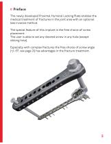
Preface The newly developed Proximal Humeral Locking Plate enables the medical treatment of fractures in the joint area with an optional less invasive method. The special feature of this implant is the free choice of screw placement. The user is able to set any desired screw in any hole (except oblong hole). Especially with complex fractures the free choice of screw angle (+/- 15°, see page 21) has advantages in the fracture treatment.
Open the catalog to page 5
Cortical Screw, locking, D=3.5mm, SH Spiral Drill, D=2.7mm, L=220mm, AO Connector Spiral Drill, D=2.7mm, L=220mm, AO Connector Cancellous Screw, locking, D=4.2mm, SH Spiral Drill, D=2.5mm, L=220mm, AO Connector Guide Wire, Steel, D=1.6mm, L=260mm, TR, w. thread
Open the catalog to page 6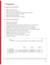
Properties Properties of the material: • • • • • • Plate material: Titanium Material of screws: TiAl6V4 ELI Easier removal of the implant after the fracture has healed Improved fatigue strength of the implant Reduced risk of cold welding Reduced risk of inflammation and allergy Properties of the implant: Multi-directional locking Anatomical plate design 6 proximal plate holes for optimal reconstruction of the humeral head 6 marginal proximal holes for fixation of soft tissue to the plate Indentations in the shaft area to facilitate the use of cerclage wire Oblong hole for optimal positioning...
Open the catalog to page 7
Indications, Contraindications & Time of operation Indications: • All stable and unstable fractures with or without shaft involvement Severe osteoporosis Existing infections in the area of the fracture In cases of skin and soft tissue problems Obesity Lack of patient compliance Time of operation: • Primary as well as secondary after swelling subsides and after temporary fixation
Open the catalog to page 8
Surgical Technique
Open the catalog to page 9
Assembling of the percutaneous guide 1 Pre-operative patient preparation • Positioning on a radiolucent surgical table • Semi-sitting angle of about 30° - 40°, shoulder should be freely moveable (optional shoulder table) • The arm should be freely moveable to allow fracture reduction • General anaesthesia, regional anaesthesia or combination can be used
Open the catalog to page 10
Exposure Anterolateral access: • Skin incision parallel to the anterior acromion and extension 5cm distally in fiber direction of the M. deltoideus. • Detachment of the pars acromialis of the M. deltoideus. Reduction Anatomical reduction of the fracture under fluoroscopy.
Open the catalog to page 11
Plate insertion • • • • Insert the plate, assembled on the percutaneous guide (recommended in Z position) Plate remains in constant contact with the bone and slide distally Align the proximal end of the plate on the Tuberculum majus Verify the correct plate position. Optional temporary fixation with guide wires, steel, D=1.6mm, L=260mm, TR, w. thread (35164-260) into proximal guide wire holes.
Open the catalog to page 12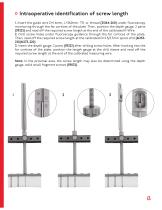
Intraoperative identification of screw length 1. Insert the guide wire D=1.6mm, L=260mm, TR, w. thread (35164-260) under fluoroscopy monitoring through the far cortices of the plate. Then, position the depth gauge, 2 parts (59222) and read off the required screw length at the end of the calibrated K-Wire. 2. Drill screw holes under fluoroscopy guidance through the far cortices of the plate. Then, read off the required screw length at the calibrated D=2.5/2.7mm spiral drill (61253220/61273-220). 3. Insert the depth gauge, 2 parts (59222) after drilling screw holes. After hooking into the far cortices...
Open the catalog to page 13
Placement of the screws Fix the plate temporarily to the bone and drill with the spiral drill, D=2.7mm, L=220mm, AO Connector (61273-220) in the oblong hole. Drilling is performed through the D=2.8mm drill sleeve (118005-10) that was placed in the tissue protection sleeve (118005-8). Then, the drill sleeve is removed and a D=3.5mm cortical screw (32351-XX) (appropriate length measured before) is inserted through the tissue protection sleeve. Advice: For optimal positioning and adjustment of the humeral length, we recommend to first fill the oblong hole. Therefore there is a centric and eccentric...
Open the catalog to page 14
Unscrew the clamping nut (118005-4) up to the black mark (see picture below), rotate the handle 180° and tighten the clamping nut by hand. Then using the spiral drill, D=2.5/2.7mm, L=220mm, AO Connector (61253-220/61273-220) to drill through the drill guide, D=2.7/2.0mm (62202) into a proximal hole. Use the screwdriver, WS 2.5 (56252-150) to insert a D=3.5mm locking cortical screw (37351XX-N) or a D=4.2mm locking cancellous screw (37422-XX-N) of appropriate length determined previously with the depth gauge, solid small fragment screws (59022).
Open the catalog to page 15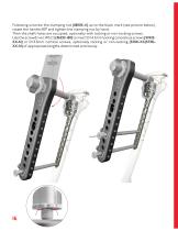
Following unscrew the clamping nut (118005-4) up to the black mark (see picture below), rotate the handle 180° and tighten the clamping nut by hand. Then the shaft holes are occupied, optionally with locking or non-locking screws. Use the screwdriver, WS 2.5 (56252-150) to insert D=4.2mm locking cancellous screws (37422XX-N) or D=3.5mm cortical screws, optionally locking or non-locking (32351-XX/37351XX-N) of appropriate lengths determined previously.
Open the catalog to page 16All I.T.S. catalogs and technical brochures
 CTN - Cannulated Tibia Nail
28 Pages
 ufs
ufs1 Page
 DHL
DHL2 Pages
 ITS
ITS2 Pages
 SCL
SCL32 Pages
 SLS
SLS24 Pages
 OL - Olecranon Locking Plate
24 Pages
 PHL
PHL24 Pages
 PHLs
PHLs20 Pages
 CLS
CLS28 Pages
 ACLS
ACLS20 Pages
 CFN
CFN32 Pages
 OLS
OLS24 Pages
 SR Sacral Rods
20 Pages
 HCS
HCS24 Pages
 TOS Twist-Off Screw
20 Pages
 TLS
TLS20 Pages
 PRS-RX
32 Pages
 HLS
HLS20 Pages
 ES
ES20 Pages
 SR
SR20 Pages
 FL
FL24 Pages
 PL - Pilon Locking Plate small
12 Pages
 FLS
FLS24 Pages
 PFL
PFL20 Pages
 DTL
DTL24 Pages
 HTO
HTO24 Pages
 PTL
PTL32 Pages
 DFL
DFL32 Pages
 CAS
CAS40 Pages
 FCN
FCN20 Pages
 HOL
HOL24 Pages
 CAL
CAL20 Pages
 DUL
DUL24 Pages


Archived catalogs


- Bone plate
- Compression plate
- Metallic compression plate
- Locking compression plate
- Distal compression plate
- Compression bone screw
- Metallic compression bone screw
- Proximal compression plate
- Arthrodesis nail
- Forearm compression plate
- Lateral compression plate
- Medial compression plate
- General purpose compression bone screw
- Tibia compression plate
- Metallic intramedullary nail
- Humerus compression plate
- Cannulated compression bone screw
- Radius compression plate
- Proximal fixation intramedullary nail
- Arthrodesis plate