PTL

PTL
The document discusses the Proximal Lateral Tibia Locking Plate, part of the Locking Reconstruction System (LRS), designed for less invasive treatment of joint fractures. It highlights the flexibility in screw placement, beneficial for complex fractures.
The plates are made from titanium, and screws from TiAl6V4 ELI, offering enhanced fatigue strength and reduced risks of cold welding and inflammation. Plates are anatomically preformed but adjustable.
Indications include stabilization of proximal tibia fractures. Contraindications include advanced osteoporosis, skin issues, obesity, and non-compliance. Surgery should occur soon after trauma or swelling reduction.
The procedure involves preparation, reduction, access, plate insertion, and screw placement. Temporary fixation with K-Wires is recommended, followed by locking cancellous and cortical screws.
Postoperative care includes positioning with a slight knee bend, passive mobilization after swelling reduction, and gradual weight-bearing increase. Implant removal is possible after six months if healed.
Specifications for screws and plates are detailed, including dimensions and materials. The Dotize® anodization process enhances titanium surface, reducing cold welding risks and improving fatigue resistance.
The LRS system offers a versatile, less invasive option for joint fractures, with flexible screw placement and enhanced material properties for effective stabilization and healing.
Cancellous screws have a diameter of 5.9mm, lengths from 28mm to 90mm. Cortical screws have a diameter of 4.5mm, lengths from 16mm to 120mm, with locking options. Instruments include guide wires, screwdrivers, drills, and depth gauges.
Guidelines for reconditioning medical devices emphasize product identification and handling. Implants are temporary stabilizers and should be removed post-consolidation. No allergic reactions to titanium noted, but possible reactions to steel.
Implants are single-use, require careful handling, and should not be combined with other producers' implants. Regular follow-ups and MRI guidelines are advised. Protective measures for contaminated products are emphasized.
Steps for cleaning, disinfection, and drying of reusable instruments are provided. Automatic cleaning using a washer-disinfector is recommended. Manual cleaning is discouraged unless necessary.
Instruments should be inspected for cleanliness and functionality. Movable parts require lubrication, and reassembly checks ensure ease of use. Adherence to manufacturer guidelines is stressed.
Delivery packaging is for transport only and unsuitable for sterilization. Hospitals must follow standard packaging guidelines and use sterile barrier systems.
Instruments and implants should be arranged for steam access. Dismantle instruments for sterilization. Use fractionated pre-vacuum procedure, following EN 285 (or EN 13060) and EN ISO 17665 standards.
Disposal should follow hospital guidelines.
Surgical instruments have a long service life but can degrade quickly if misused. Non-functional instruments must be disposed of. Returned products must be cleaned, disinfected, inspected, and sterilized.
Instructions for reconditioning medical devices are validated. Deviations should be evaluated for efficiency and potential negative consequences. Contact information is provided for inquiries.
Patients should be informed about post-implantation behavior and report any negative changes or incidents.
Symbols indicate prescription, single use, expiry date, charge number, sterilization methods, order number, material, package content, size, instructions, latex-free status, non-sterile status, and compliance with standards.
Catalog excerpts

Implants trauma Proximal Lateral Tibia Locking Plate
Open the catalog to page 1
CAUTION: Federal Law (USA) restricts this device to sale by or on the order of a board certified physician. WARNING: If there is no sufficient bone healing, wrong or incomplete postoperative care, plate might break. All ITS plates are preformed anatomically as a matter of principle. If adjustment of the plate to the shape of the bone is required, this is possible by carefully bending gently in one direction once. Particular care is required when bending in the region of a plate hole, as deformation of the plate may lead to a failure of the locking mechanism. The plate must not be buckled or bent...
Open the catalog to page 2
1. Introduction P. 5 Preface P. 6 Screws P. 7 Properties P. 7 Preoperative identification of screw length P. 8 Indications & Contraindications P. 8 Time of operation 2. Surgical Technique P. 10 Pre-operative patient preparation P. 10 Assembling of the insertion guide/extraction instrument P. 11 Reduction P. 11 Access P. 12 Plate insertion P. 13 Temporary fixation with K-Wires P. 14 Reduction instrument P. 15 Intraoperative identification of screw length P. 16 Placement of the screws P. 17 Drilling optionally P. 20 Disassembling of the insertion guide P. 21 Postoperative treatment P. 21 Explantation...
Open the catalog to page 3
Preface The newly developed LRS System - Locking Reconstruction System enables the medical treatment of fractures in the joint area with an optional less invasive method. The special feature of this implant is the free choice of screw placement. The user is able to set any desired screw in any hole. The system provides the opportunity to operate with or without a drill block in the joint area. Especially with complex fractures the free choice of screw angle (+/- 15°, see page 23) has advantages in the fracture treatment.
Open the catalog to page 5
Cancellous Screw, Locking, D=5.9mm Spiral Drill, D=3.5mm, L=280mm, AO Connector Screwdriver Shank, PRS, Solid, WS 3.5, L=230mm, AO Connector Spiral Drill, D=3.5mm, L=280mm, AO Connector Screwdriver Shank, PRS, Solid, WS 3.5, L=230mm, AO Connector Spiral Drill, D=3.2mm, L=280mm, AO Connector Screwdriver Shank, PRS, Solid, WS 3.5, L=230mm, AO Connector Cortical Screw, Locking, D=4.5mm Spiral Drill, D=3.2mm, L=280mm, AO Connector Screwdriver Shank, PRS, Solid, WS 3.5, L=230mm, AO Connector
Open the catalog to page 6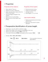
Properties Properties of the material: • Plate material: Titanium • Material of screws: TiAl6V4 ELI • Easier removal of the implant after the fracture has healed • Improved fatigue strength of the implant • Reduced risk of cold welding • Reduced risk of inflammation and allergy Multi-directional locking Anatomical plate design Left/right version Plate lengths: 4, 7, 12, 17-hole Less invasive method: • Radiolucent handle and drill block close to joint • Reduction instrument for easier reduction Preoperative identification of screw length • • • • Preparing a x-ray with a 50mm calibration plate...
Open the catalog to page 7
Indications, Contraindications & Time of operation Indications: For stabilization of fractures of the proximal tibia • Proximal shaft fractures • Metaphyseal fractures • Intra-articular fractures With advanced osteoporosis In cases of skin and soft tissue problems above the lateral epicondylus Obesity Lack of patient compliance Time of operation: • Primary: Within the first hours after trauma • Secondary: After swelling subsides, intermediate fixation with external fixation or extension
Open the catalog to page 8
Surgical Technique
Open the catalog to page 9
Pre-operative patient preparation • • • • Position the patient supine on a radiolucent table Leg freely movable X-rays of the lateral and anterior-posterior proximal tibia should be possible To flex the knee joint, a roll can be placed below the knee Assembling of the insertion guide 1 Assemble the insertion guide on the plate with the fixation screw (118002-7) Assembling of the clamping bolt with flat wrench, WS 11 (70011) Assembling of the reduction instrument
Open the catalog to page 10
Anatomic reposition of the fracture In intra-articular fractures reconstruct and stabilize the whole joint Possible temporary fixation with K-Wires Following x-ray control Straight, short, skin incision (see picture below) from Gerdy‘s tubercle 50mm to distal Open the space between the anterior tibial muscle and the periosteum Insert the plate between the periosteum and the muscle Anterolateral arthrotomy providing good control of the reduction
Open the catalog to page 11
Plate insertion • Insert the plate, assembled on the insertion guide, between the anterior tibial muscle and periosteum • Distal end of the plate should remain in constant contact with the bone • Position the proximal end of the plate against the lateral condyle (plate must lie flat up against the condyle. If it‘s problematic to find the correct position, enlarge the incision) • Verify the correct plate position under fluoroscopy and temporarily secure it with the tissue protection sleeve (118003-11), drill sleeve, D=1.7/3.6mm (118003-9/118003-10) and the inserted guide wire, steel, D=1.6/3.2mm,...
Open the catalog to page 12
Temporary fixation with K-Wires Fixation with K-Wires passed through tissue protection sleeves (118003-11) and inserted drill sleeve D=1.7/3.6mm (118003-9/118003-10) can be performed as soon as plate and bone have been optimally aligned. Distal fixation follows after proximal fixation. Insert trocar (57042) through the tissue protection sleeve (118003-11) in the most distal hole of the plate (guiding instrument) and advance to the plate after stab incision. Then, insert the retaining sleeve (118003-16), screw it onto the plate and place the D=1.6mm guide wire (35164-260) through the retaining...
Open the catalog to page 13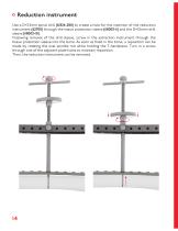
Reduction instrument Use a D=3.2mm spiral drill (61324-280) to create a hole for the insertion of the reduction instrument (62700) through the tissue protection sleeve (118003-11) and the D=3.6mm drill sleeve (118003-10). Following removal of the drill sleeve, screw in the extraction instrument through the tissue protection sleeve into the bone. As soon as fixed in the bone, a reposition can be made by rotating the oval spindle nut while holding the T-handpiece. Turn in a screw through one of the adjacent plate holes to maintain reposition. Then, the reduction instrument can be removed.
Open the catalog to page 14All I.T.S. catalogs and technical brochures
 CTN - Cannulated Tibia Nail
28 Pages
 ufs
ufs1 Page
 DHL
DHL2 Pages
 ITS
ITS2 Pages
 SCL
SCL32 Pages
 SLS
SLS24 Pages
 OL - Olecranon Locking Plate
24 Pages
 PHL
PHL24 Pages
 PHLs
PHLs20 Pages
 CLS
CLS28 Pages
 ACLS
ACLS20 Pages
 CFN
CFN32 Pages
 OLS
OLS24 Pages
 SR Sacral Rods
20 Pages
 HCS
HCS24 Pages
 TOS Twist-Off Screw
20 Pages
 TLS
TLS20 Pages
 PRS-RX
32 Pages
 HLS
HLS20 Pages
 ES
ES20 Pages
 SR
SR20 Pages
 FL
FL24 Pages
 PL - Pilon Locking Plate small
12 Pages
 FLS
FLS24 Pages
 PFL
PFL20 Pages
 DTL
DTL24 Pages
 HTO
HTO24 Pages
 DFL
DFL32 Pages
 CAS
CAS40 Pages
 FCN
FCN20 Pages
 HOL
HOL24 Pages
 CAL
CAL20 Pages
 DUL
DUL24 Pages


Archived catalogs


- Bone plate
- Compression plate
- Metallic compression plate
- Locking compression plate
- Distal compression plate
- Compression bone screw
- Metallic compression bone screw
- Proximal compression plate
- Arthrodesis nail
- Forearm compression plate
- Lateral compression plate
- Medial compression plate
- General purpose compression bone screw
- Tibia compression plate
- Metallic intramedullary nail
- Humerus compression plate
- Cannulated compression bone screw
- Radius compression plate
- Proximal fixation intramedullary nail
- Arthrodesis plate