


UOL

UOL
Catalog excerpts
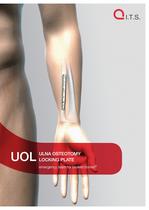
UOL ULNA OSTEOTOMY LOCKING PLATE emergency team for broken bones®
Open the catalog to page 1
CONTENTS Preface 3 Screws 4 Properties 5 Indications & Contraindications 5 Assembling of the instruments 6 Positioning of the patient 7 Exposure 7 Plate insertion 8 Placement of the tensile bolts Surgical Technique Preface 9 Shortening Reduction 16 Placement of the screws 19 Removal of the instruments 22 Postoperative treatment 24 Summary Information 12 25 Order information 26 Locking 28 Dotize® 28 Sterilization guidelines 30
Open the catalog to page 2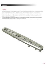
Preface Preface: The Ulna Osteotomy Locking Plate provides a plate system (hybrid system) to be studded with locking screws and compression screws, which is specially adapted to the anatomic and biomechanic requirements after shortening osteotomy of the distal ulna. In a single device, the Ulna Osteotomy Locking Plate allows for unique coplanar orientation of the incisions with rotation-stable shortening and the option for compression. The standardization of a plurality of surgical procedures into a single device system obtained thereby increases and secures the quality of the surgical procedure....
Open the catalog to page 3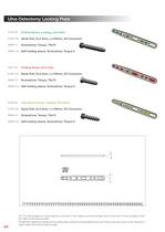
Ulna Osteotomy Locking Plate 37301-XX Cortical Screw, Locking, D=3.0mm 61243-100 Spiral Drill, D=2.4mm, L=100mm, AO Connector 56095-70 Screwdriver, Torque, T9x70 56095-70-2 Self-holding sleeve, Screwdriver, Torque 9 32271-XX Cortical Screw, D=2.7mm 61203-100 Spiral Drill, D=2.0mm, L=100mm, AO Connector 56095-70 Screwdriver, Torque, T9x70 56095-70-2 Self-holding sleeve, Screwdriver, Torque 9 37302-XX Cancellous Screw, Locking, D=3.0mm 61203-100 Spiral Drill, D=2.0mm, L=100mm, AO Connector 56095-70 Screwdriver, Torque, T9x70 56095-70-2 Self-holding sleeve, Screwdriver, Torque 9 All I.T.S. locking...
Open the catalog to page 4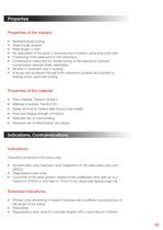
• Multidirectional locking • Anatomically shaped • No dislocation of the parts of the bone due to fixation using long-bore hole • Positioning of the plate prior to the osteotomy • Compression instrument for simple joining of the osteotomy surfaces (compression strength freely selectable) • No loss of correction due to locking • A screw can be placed through both osteotomy surfaces as a tension or fixating screw, optionally locking • Plate material: Titanium Grade 2 • Easier removal of implant after fracture has healed • Improved fatigue strength of Implant • Reduced risk of cold bonding • Reduced...
Open the catalog to page 5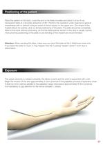
Positioning of the patient Place the patient on his back, cover the arm to be freely movable and place it on an X-ray transparent table at a shoulder abduction of 90°. Perform the operation under regional or general anaesthesia with or without using an arrest of blood supply on the upper arm. The shape of the implant allows for palmar, ulnar or dorsal positioning of the plate. The plate should be completely fitted to the bone without protruding. As the the distal palmar section of the ulna is usually curved, more proximal positioning of the plate or pre-bending of the implant are recommended....
Open the catalog to page 7
Plate insertion After opening the forearm fascia, mobilize bluntly the belly of the FCU (M. flexor carpi ulnaris) at its insertion point at the ulna and retract it medial using Hohmann retractors. Define the optimal position of the plate and incise the dorsal forearm fascia in the designated osteotomy area. 08
Open the catalog to page 8
Placement of the tension bolts Place the assembled osteotomy system upon the ulna osteotomy plate, which is attached to the ulna using the plate holes alternatingly from the outside centrad; distally with D=3.0mm locking cancellous screws (37302-XX) or D=3.0mm locking cortical screws (37301-XX) (spiral drill, D=2.0mm, L=100mm, AO Connector (61203-100) for locking cancellous screw / spiral drill, D=2.4mm, L=100mm, AO Connector (61243-100) for locking cortical screw), proximally with 2 tension bolts (680859) after inserting the drill guide, D=2.0mm (62208) for the tension bolt and a D=2.0mm bore...
Open the catalog to page 9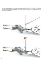
The bore diameter depends on the choice of the screw. (spiral drill, D=2.0mm, L=100mm, AO Connector (61203-100) for locking cancellous screw / spiral drill, D=2.4mm, L=100mm, AO Connector (61243-100) for locking cortical screw). 10
Open the catalog to page 10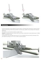
Shortening Incise the periosteum at the osteotomy site and retract it minimally before performing, using the incision gage and producing as little heat as possible, two atraumatic, parallel cuts according to the measured shortening. The maximum recommended osteotomy length is 6mm. Caution: In osteoporotic bones, traction bolts may tilt due to high traction forces (malformation of drilled holes in osteoporotic bone). The thickness of the saw blade may amount to 0.7mm maximally. We recommend a thickness of the saw blade amounting to 0.5–0.7mm in order to achieve precision. 12
Open the catalog to page 12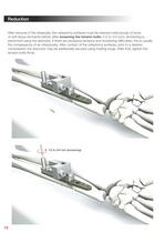
Reduction After removal of the dissecate, the osteotomy surfaces must be cleaned meticulously of bone or soft tissue remnants before, after loosening the tension bolts (1/2 to 3/4 turn), shortening is performed using the setscrew. If there are excessive tensions and shortening difficulties, this is usually the consequence of an interponate. After contact of the osteotomy surfaces, prior to a desired compression the reduction may be additionally secured using holding tongs. After that, tighten the tension bolts firmly. 1/2 to 3/4 turn (loosening) 16
Open the catalog to page 16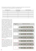
If shortening of more than 6mm is desired, two subsequent osteotomies may be performed. For recommended OT-widths please refer to table stated below. Shortening in mm First Osteotomy Second Osteotomy 0-6 required length - 7 4 3 8 5 3 9 6 3 10 6 4 11 6 5 12 6 6 13 7 6 Any desired shortening of 7-13mm may be performed following the initial OT by manual support and protected against rotation using a clamp, without using the adjusting screw on compression (for OT-widths, please see table above). As a result, the drill holes will stay undeformed to the greatest extent even in osteoporotic bone, while...
Open the catalog to page 18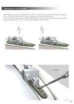
Placement of the screws After making a bore with the spiral drill, D=2.0mm, L=100mm, AO Connector (61203-100), place a D=2.7mm cortical screw (32271-XX) as a fixation screw into the oblique bore. The cortical screw may optionally be used as a tension screw (bore into the corticalis near the plate using a spiral drill, D=2.7mm, L=100mm, AO Connector (61243-100)). D=2.0 mm 19
Open the catalog to page 19All I.T.S. catalogs and technical brochures
 CTN - Cannulated Tibia Nail
28 Pages
 ufs
ufs1 Page
 DHL
DHL2 Pages
 ITS
ITS2 Pages
 SCL
SCL32 Pages
 SLS
SLS24 Pages
 OL - Olecranon Locking Plate
24 Pages
 PHL
PHL24 Pages
 PHLs
PHLs20 Pages
 CLS
CLS28 Pages
 ACLS
ACLS20 Pages
 CFN
CFN32 Pages
 OLS
OLS24 Pages
 SR Sacral Rods
20 Pages
 HCS
HCS24 Pages
 TOS Twist-Off Screw
20 Pages
 TLS
TLS20 Pages
 PRS-RX
32 Pages
 HLS
HLS20 Pages
 ES
ES20 Pages
 SR
SR20 Pages
 FL
FL24 Pages
 PL - Pilon Locking Plate small
12 Pages
 FLS
FLS24 Pages
 PFL
PFL20 Pages
 DTL
DTL24 Pages
 HTO
HTO24 Pages
 PTL
PTL32 Pages
 DFL
DFL32 Pages
 CAS
CAS40 Pages
 FCN
FCN20 Pages
 HOL
HOL24 Pages
 CAL
CAL20 Pages
 DUL
DUL24 Pages


Archived catalogs


- Bone plate
- Compression plate
- Metallic compression plate
- Locking compression plate
- Titanium compression plate
- Distal compression plate
- Compression bone screw
- Metallic compression bone screw
- Proximal compression plate
- Arthrodesis nail
- Forearm compression plate
- Lateral compression plate
- Medial compression plate
- Tibia compression plate
- General purpose compression bone screw
- Metallic intramedullary nail
- Humerus compression plate
- Radius compression plate
- Cannulated compression bone screw
- Arthrodesis plate