- Catalogs
- Jeil Medical Corporation
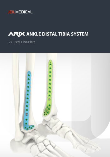
- Orthopedic - ARIX Ankle System Lateral Distal Fibula Plate
Orthopedic - ARIX Ankle System Lateral Distal Fibula Plate
1 /20Pages

Orthopedic - ARIX Ankle System Lateral Distal Fibula Plate
1 /20Pages
Catalog excerpts
ANKLE SYSTEM Lateral Distal Fibula Plate
Open the catalog to page 1
Indications Features Surgical Technique Ordering information - Plate - Screws - Instruments Set Configuration Sug
Open the catalog to page 2
ARIX Fibula Plate is indicated for the following conditions ‧AO-OTA 44 B (trans-syndesmotic) , C (supra-syndesmotic) lateral malleolar fractures ‧Non-unions after lateral malleolar fracture fixation ‧ tabilization of osteotomies of the metaphyseal and diaphyseal region of the distal fibula, especially in S osteoporotic bo
Open the catalog to page 3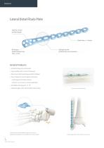
Lateral Distal Fibula Plate Hole for 1.6 mm positioning pin Shaft holes: 3 ~ 8 holes Minimized distal thickness less than 1.3 mm Oblong holes for syndesmosis screw insertion General Features • Anatomically pre-contoured • Low profile with 2.0 mm thickness • No screw head overhang avoids irritation • Four choices in screw types and sizes - Locking and cortical screws - 2.8 mm or 3.5 mm in screw diameter • Variable locking up to ± 15° • Plates length with 3 to 8 shaft screw holes No screw head protrusion Tapered screw hole enables surgeons to control appropriate trajectory for syndesmosis screw...
Open the catalog to page 4
Refined shape of the plate head is based on the bone anatomy • Posteroinferior end of distal fibula corresponds to the recess for the posterior talo-fibular ligament(PTFL). • Screw holes over posterior talo-fibular ligament(PTFL) is redundant due to its thickness which only allows placement of very short screws. • No screw penetration in the recess for PTF ligament minimizes soft tissue irritation & potential articular cartilage damage. Lateral View Ø 2.8 mm & Ø 3.5 mm locking- or cortical screws applicable No screw penetration in recess for posterior talo-fibular ligament Inferior View Clinical...
Open the catalog to page 5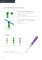
Lateral Distal Fibula Plate - continued STARIX Screw with self-retaining function • Internal recess T10 according to international standard • Minimizes the risk of cam-out and recess breakage • Allows higher torque transmission • Optimal self-retaining function achieved through precision machining Variable Locking Interface with Locking Screw • Poly-axial screw insertion • Angle range: ±15° • Plate-screw locking interface Screw Options Self-retaining function of STARIX screw Allows easy screw pick up from the box and prevents screw fall out
Open the catalog to page 6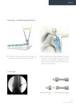
Instrument – Variable Angle Drill Sleeve ❶ he variable angle drill sleeve enables the surgeons to T insert locking screws with preferred angle in range of +/ -15°. ❷ he drill sleeve handle facilitates engaging the drill sleeve T into the screw holes. Assemble the sleeve handle to the drill sleeve. Once the drill guide is engaged to the screw hole by turning it clockwise, disconnect the drill sleeve handle by simply pulling it out. C-Arm View Variable angle drill sleeve 111-172 Variable angle drill sleeve handle 111-157 Lateral Distal Fibula P
Open the catalog to page 7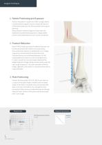
Surgical Technique 1. Patient Positioning and Exposure Position the patient in supine and make a straight lateral or posterolateral surgical incision to expose the fracture of the fibula based upon the fracture pattern and surgical planning. When posterior malleolar fragment is planned to be stabilized via posterolateral approach, a floppy lateral position with posterolateral incision can be considered. Most AO 44 B simple spiral lateral malleolar fractures can be reduced directly with a Weber or lion jaw clamp. Once anatomical reduction is verified with c arm images a lag screw can be placed...
Open the catalog to page 8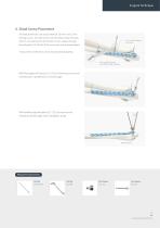
Surgical Technique 4. Distal Screw Placement distal plate holes can accept either Ø 2.8 mm or Ø 3.5 mm All locking screws. To insert screws into the distal cluster of holes, drill 2.7 mm drill bit (112-35-703) for 3.5 mm screws through 2.7 mm drill Guide for 3.5 screws the drill guide (111-203 for Ø 3.5 mm screw) to the desired depth. *Instruments for Ø2.8mm screw are provided separately. 3.6 mm drill Guide for over-drilling & lag screwing With fixed angle drill sleeve (111-173), the locking screw can be inserted only in predefined or nominal angle. With variable angle drill sleeve (111-172),...
Open the catalog to page 9
Surgical Technique 4. Distal Screw Placement - continued Measure the screw length by using the depth gauge (111-086). Insert 3.5 mm locking or cortical screws by connecting the T10 driver (113-HF-616) to the driver handle (111-206). CAUTION: Use the maximum number of screws based on the indication to get the maximum stability Confirm screw placement under fluoroscopy. Required Instruments Depth Guide 111-086 ARIX Ankle System
Open the catalog to page 10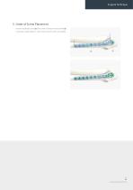
Surgical Technique 5. Order of Screw Placement Insert most distal screw(❶) first, then one of proximal screws(❷) to prevent plate rotation. Then insert rest of screws as needed. Lateral Distal Fibula
Open the catalog to page 11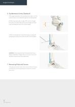
Surgical Technique 6. Syndesmosis Screw (Optional) the surgeon decided to insert syndesmosis screws, a 3.5 mm If cortical screws can be utilized through the two oblong holes. Drill the screw hole with an angle of 30° anterior to target the center of the tibia. Measure the screw length and insert screw according to usual screw insertion steps. Confirm screw placement under fluoroscopy. Closing and postoperative protocol are at the discretion of the surgeon. WARNING: Screws placed across the syndesmosis have a higher probability of fatigue failure of screws due to the repetitive motion across the...
Open the catalog to page 12
Lateral Distal Fibula Plate - Ordering information Lateral Distal Fibula Plate
Open the catalog to page 13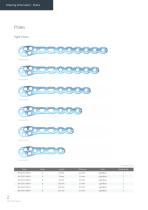
Ordering information - Plates Code Holes Length Thickness Color Set Quantity ARIX Ankle System
Open the catalog to page 14
Ordering information - Plates Code Holes Length Thickness Color Set Quantity Lateral Distal Fibula Plate
Open the catalog to page 15
Ordering information - Screws Code Length Color Set Quantity 0 3.5 mm Cortical Screws (Non-Locking) Code Length Color Set Quantity Code Length Gold Optional Gold Optional Gold Optional Gold Optional Gold Optional Gold Optional Gold Optional Gold Optional ARIX Ankle System
Open the catalog to page 16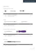
Ordering information - Instruments Code Description Set Quantity 111-172 Drill Sleeve for 0 2.7 mm Drill Bit, Variable Angle 111-173 Drill Sleeve for 0 2.7 mm Drill Bit, Fixed Angle 111-157 Variable Angle Drill Sleeve Handle Code Description Se t Quantity 112-35-703 Drill Bit 0 2.7 mm for 0 3.5 mm Screws 112-35-701-L Lag Drill Bits for 0 3.5 mm Screws Code Description Set Quantity 113-HF-616 Screwdriver Shaft for 0 3.5 mm Screws 2 Code Description Set Quantity 111-086 Depth Gauge for 0 2.8 mm, 0 3.5 mm Screws 1 Lateral Distal Fibula Plate
Open the catalog to page 17Archived catalogs
 Cranial - Sterile NS Kit
2 Pages
 Cranial - LeForte Neuro System
16 Pages
 Orthopedic - ARIX Humerus System
20 Pages
 Orthopedic - ARIX Elbow
44 Pages
 Cranial - Speedy Flap System
4 Pages
 ARIX System Product Catalog
62 Pages
 Jeil Customized Implant
12 Pages
 Cranial - Sterile NS System
16 Pages
 ARIX Ulna Osteotomy System
16 Pages
 Orthopedic - Arix Hand System
20 Pages
 ARIX WRIST SYSTEM
36 Pages
 OMF - Facial Bandage
2 Pages


- Dental material
- Bone plate
- Compression plate
- Metallic compression plate
- Dental restoration material
- Locking compression plate
- Surgery forceps
- Grasping forceps
- Dental implant
- Titanium dental implant
- Stainless steel forceps
- Titanium compression plate
- Reusable forceps
- Distal compression plate
- Orthopedic clothing
- Interbody fusion cage
- Compression bone screw
- Conical dental implant
- Metallic compression bone screw
- Biocompatible dental material