- Catalogs
- Jeil Medical Corporation
- Orthopedic - ARIX Clavicle System
Orthopedic - ARIX Clavicle System
1 /36Pages

Orthopedic - ARIX Clavicle System
1 /36Pages
Catalog excerpts

CLAVICLE SYSTEM 2.5 / 3.5 Clavicle Plate
Open the catalog to page 1
Surgical Technique - Lateral Hook Plate - Plate and Screw Removal Ordering Information - Clavicle Superior Lateral Plates - Clavicle Superior Midshaft Plates - Clavicle Hook Plates - ARIX Clavicle System Screws - ARIX Clavicle System Instruments
Open the catalog to page 2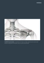
The ARIX Clavicle System is indicated for the fixation of single, segmental and comminuted fractures, osteotomies, mal-unions, and non-unions of the clavicle.
Open the catalog to page 3
ARIX Clavicle Plate The ARIX Clavicle System is a locking plate system for clavicle fractures. The Clavicle Plate provides an optimized fit for the clavicle bone. The ARIX Clavicle System also offers a variety of screws to help a provide flexible surgical technique for users. General Features Pre-contoured Shape • Anatomically Pre-contoured based on bone data analysis • Left & Right Plate Variations for anatomical fitting • Plate Thickness 3.5 mm • Lateral, Midshaft & Hook Plates available Limited Contact Design for better blood supply Titanium 6Al 4V Alloy, ASTM F-136 Lateral Plate • Fracture...
Open the catalog to page 4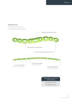
Midshaft Plate • Fractures of the clavicle shaft • Fracture of the clavicular midshaft Bidirectional Compression Hole Unidirectional Compression Hole Ø 3.5 mm Variable Locking Hole up to ±15° Pre-contoured Shape based on bone data analysis Limited Contact Design for better blood supply Smoothing Edge Design for Less Soft tissue Irritation Two Variations of Curvatures for Better Fitting • Increased Curvature • Decreased Curvature
Open the catalog to page 5
Features - continued Hook Plate • Acromioclavicular joint dislocation • Fractures of the lateral clavicle Hook Gradient for optimal anatomical fitting Bidirectional Compression Hole Ø 3.5 mm Variable Locking Hole up to ±15° 102° Various Choices of Hook Depths 12 mm / 15 mm / 18 mm ARIX Clavicle System Unidirectional Compressio
Open the catalog to page 6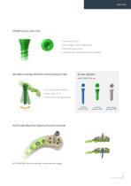
STARIX Screw with T10 • Prevents Cam-out • Allows Higher Torque Application • Self-Retaining function • Locking & Non-Locking Variations available Variable Locking Interface with Locking Screw Screw Options with STARIX Pick-up • Poly-axial Screw Insertion • Angle range: ±15° • Plate-Screw Locking Interface Drill Guide Block for Optimal Screw Insertion Drill Guide Block ensures optimal screw insertion angles
Open the catalog to page 7
1. Surgical Technique - General
Open the catalog to page 9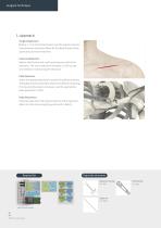
Surgical Technique Surgical Approach Make a 3 - 5 cm horizontal incision over the superior clavicle. Subcutaneous dissection allows for the identification of the supraclavicular nerve branches. Fracture Reduction Reduce the fracture and use fluoroscopy to confirm the reduction. The use of reduction forceps(111-154) can be very helpful in maintaining the reduction. Plate Selection Select the appropriate plate to match the patient anatomy. The plates are precontoured to reduce the need of contouring. If contouring the plate is necessary, use the appropriate plate benders(111-180). Plate Placement...
Open the catalog to page 10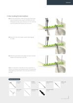
2. Non-Locking Screw Insertion 1 Place the drill guide(111-260) into the appropriate plate hole and prepare a hole using the drill bit(112-35-703). If drilling bicortically, place a retractor(111-197) under the clavicle to protect the neurovascular structures. 2 Measure for the screw length using the depth gauge 3 Select the appropriate screw length and insert using the Note: It is important to note that if an axial compression is desired, non-locking screws should be used in the compression holes before any circular holes on the same side of the fracture are filled. Required Instruments Drill...
Open the catalog to page 11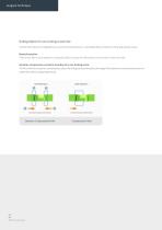
Surgical Technique Drilling Option for non-locking screw hole Use the drill sleeve or drill guide for an eccentric(compression) or neutral(buttress) insertion of the appropriate screw. Neutral insertion If the screw has to be inserted in a neutral position, locate the drill sleeve on the center of the oval hole. Dynamic compression, eccentric insertion of a non-locking screw To drill a hole for a dynamic compression, place the drill guide eccentrically at the edge of the dynamic compression portion of plate hole, without applying pressure. Drill Position Drill Position Compression Direction Dynamic...
Open the catalog to page 12
3. Locking Screw Insertion 1 Place the drill guide(111-260) into the appropriate plate hole and prepare a hole using the drill bit(112-35-703). Read the corresponding screw length using the depth gauge(111-086). 2 Select appropriate screw length and insert it using the 3 Insert the remaining screws as needed to complete the Required Instruments Drill Sleeve Drill Sleeve Drill Sleeve Handle Drill Guide Drill Bits Depth Gauge Screwdriver Shaft Screwdriver Handle
Open the catalog to page 13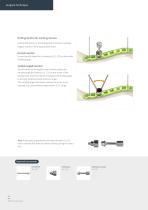
Surgical Technique Drilling Option for Locking Screws Use the drill sleeve or the drill guide for normal or variable angled insertion of the appropriate screw. Normal Insertion Locate the drill sleeve for uni-direction(111-173) on the center of locking hole. Variable angled insertion To drill a hole for an angled screw insertion, place the variable angle drill sleeve(111-171) on the center of the locking hole. Insert the drill bit and adjust the drilling angle to the user preferred screw insertion angle. The variable angle drill sleeve enables the screw to be inserted at a user preferred angle...
Open the catalog to page 14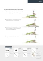
4. Locking Screw Insertion for Ø 2.5 mm Screws 1 Place the drill guide block(111-196-X) onto the distal end of the plate so that the screw threads into the threaded plate hole and the pin seats into the Guide Pin hole. 2 Insert the drill sleeve(111-101) into the desired hole. Leave the sleeve in place until after the screw is inserted. 3 Drill through the sleeve to the desired depth using the drill bit(112-25-701). Remove drill sleeve and read the screw length using the depth gauge(111-075). 4 Insert the 2.5 mm locking screw through the guide sleeve Required Instruments Drill Sleeve Drill Sleeve...
Open the catalog to page 15
2. Surgical Technique - Lateral Hook Plate
Open the catalog to page 17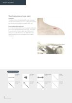
Surgical Technique Plate fixation(Lateral hook plate) Exposures The clavicle and AC joint are exposed along the anterosupe- rior subcutaneous border. A 3 cm to 5 cm incision is centered over the fracture site ending just lateral to the AC joint. Fracture/Dislocation Reduction In the case of a fracture, the fracture is exposed and debrided of the interposed hematoma and soft tissues. The fracture is reduced and the AC joint is identified. In the case of a dislocation, re-align the AC Joint by manipulation, and temporarily fixate the joint with a guide pin(111-068-3) if preferred. Required Instruments...
Open the catalog to page 18Archived catalogs
 Cranial - Sterile NS Kit
2 Pages
 Cranial - LeForte Neuro System
16 Pages
 Orthopedic - ARIX Humerus System
20 Pages
 Orthopedic - ARIX Elbow
44 Pages
 Cranial - Speedy Flap System
4 Pages
 ARIX System Product Catalog
62 Pages
 Jeil Customized Implant
12 Pages
 Cranial - Sterile NS System
16 Pages
 ARIX Ulna Osteotomy System
16 Pages
 Orthopedic - Arix Hand System
20 Pages
 ARIX WRIST SYSTEM
36 Pages
 OMF - Facial Bandage
2 Pages


- Dental material
- Bone plate
- Compression plate
- Metallic compression plate
- Dental restoration material
- Locking compression plate
- Surgery forceps
- Grasping forceps
- Dental implant
- Titanium dental implant
- Stainless steel forceps
- Titanium compression plate
- Reusable forceps
- Distal compression plate
- Orthopedic clothing
- Interbody fusion cage
- Compression bone screw
- Conical dental implant
- Metallic compression bone screw
- Biocompatible dental material