- Catalogs
- Jiangsu DINGS’ Intelligent Control Technology Co.
- GENERAL CATALOG


GENERAL CATALOG
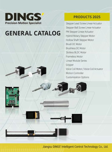
GENERAL CATALOG
DINGS’ Stepper Lead Screw Linear Actuators are available in eight sizes, from 14 mm (NEMA 6) to 86 mm (NEMA 34). They offer four form factors: External, Non-Captive, Electric Cylinder (Captive), and Kaptive. The actuators provide over 20 different travels/step, ranging from 0.00006 inch to 0.005 inch. Options include micro-stepping, various step motor angles, and a maximum linear thrust force of 2,400N. Additional features such as brake, Teflon coating, encoder, and manual knob are available.
The part number is constructed using a specific code that includes motor size, actuator type, motor step angle, motor length, rated current per phase, lead screw code, number of lead wires, lead screw length, surface treatment, end machining, nut style, and additional options like encoder or brake.
The document provides a detailed table for selecting the lead screw code based on motor travel per step and screw diameter, with conversions between metric and imperial systems.
To select the appropriate motor/lead screw combination, consider the motor size based on force requirements and the screw lead based on force and speed requirements. Additional factors include duty cycle, system life, environmental considerations, positional repeatability, and more. Physical testing is recommended for accurate selection.
This section explains the basic principles of lead screw technology, including terminology such as lead, pitch, accuracy, repeatability, and load types. It also covers the types of linear actuators and considerations for vibration, noise, static and dynamic loads, and torque requirements.
Factors like lubrication, end machining, fixity, column strength, critical speed, and backlash are discussed. The document emphasizes the importance of understanding these elements for optimal actuator performance.
The document provides an overview of stepper motors used in lead screw linear actuators, detailing the step sequence for both bipolar and unipolar configurations. It highlights the importance of phase sequence conversion for achieving half-step stepping.
General Specifications
The lead screws are made from 303 stainless precision cold-rolled steel, with optional Teflon coating. Standard screw accuracy is 0.0071 inch/foot, and screw straightness is 0.15mm/300mm. Efficiency ranges from 35% to 85%, depending on the lead and use of anti-backlash nuts. Operating temperatures range from -20°C to 55°C, with storage conditions requiring a clean, ventilated environment free from corrosive gases.
Size 6 (14mm) Series
This series features a 14mm square mounting footprint and provides a maximum thrust force of 19N. The motor characteristics include a voltage of 6.6V, current of 0.3A, and resistance of 22Ω. Various lead screw options are available, with travel per step ranging from 0.0015mm to 0.04mm.
Size 8 (20mm) Series
The 20mm series offers up to 45N of continuous thrust with a mounting footprint of less than 1 in². Motor characteristics vary, with options for different voltages and currents. Lead screw options provide travel per step from 0.0015mm to 0.04mm.
Size 11 (28mm) Series
This series provides over 140N of continuous thrust, with motor characteristics including voltages from 2.1V to 4.55V and currents from 0.5A to 1.6A. Lead screw options offer travel per step from 0.0016mm to 0.0508mm.
Size 14 (35mm) Series
The 35mm series is designed for applications requiring up to 230N of continuous thrust. Motor characteristics include voltages from 2.7V to 12V and currents from 0.5A to 1.5A. Lead screw options provide travel per step from 0.002mm to 0.0635mm.
Dimensional Drawings and Stroke Specifications
The document includes detailed dimensional drawings for various actuator types, including external, non-captive, and kaptive actuators. Stroke specifications are provided for customization, with contact information for DINGS' representatives for further assistance.
Speed Thrust Curves
Speed thrust curves are provided for different sizes and configurations, illustrating the relationship between speed, thrust, and load limits. Testing conditions are specified, recommending a 50% thrust margin for optimal performance.
The document outlines the specifications for stepper motors, including insulation class B, a temperature rise of 80°C, and an ambient temperature range of -20°C to 55°C. The motors are available in various sizes, with different voltage, current, resistance, and inductance specifications.
Lead Screw and Travel per Step
Various lead screw diameters and leads are available, with travel per step values provided for different step angles. Customization options for motor wiring and screw lead are available.
Dimensional Drawings
The document includes detailed dimensional drawings for different actuator types, including non-captive, external, and electric cylinder actuators. All drawings are ISO compliant and available in 3D models.
Speed Thrust Curves
The document provides speed thrust curves for different motor sizes and configurations, with recommended load limits and test conditions specified. The curves illustrate the relationship between speed, thrust, and pulse rates.
Installation Guide
The guide provides precautions for using screw stepper motors, including installation structures and general drive connection methods. It emphasizes avoiding radial force on screws, maintaining proper lubrication, and operating within specified temperature ranges.
Troubleshooting
Common failure causes and processing methods are outlined, including solutions for motor not running, abnormal operation, vibration, noise, abnormal heating, step loss, and insufficient thrust.
Accessories and Options
Various accessories and options are available, including anti-backlash nuts, encoders, and power-off brakes. Specifications for different motor sizes and configurations are provided.
External Nut Strength
The document specifies recommended screw sizes and installation torque for different motor sizes and nut types.
Stepper Ball Screw Linear Actuator
DINGS' external ball screw linear actuators are available in six standard sizes, with maximum thrust reaching 1600N. Encoder options are available, and part number construction is detailed.
This document provides detailed specifications and options for stepper ball screw linear actuators, including motor sizes, types, and configurations. It covers various series based on motor size, from size 6 (14mm) to size 23 (57mm), and includes information on motor characteristics, ball screw specifications, and speed thrust curves.
- Motor Sizes: Available in sizes 6, 8, 11, 14, 17, and 23, corresponding to NEMA sizes 6, 8, 11, 14, 17, and 23.
- Motor Types: External linear with options for single, double, and triple stack configurations.
- Step Angle: 2-phase motors with 1.8° or 0.9° step angles.
- Ball Screw Codes: Various codes indicating lead and diameter, such as BS2 for 2mm lead.
- Thread Direction: Right-hand thread standard.
- End Machining: Options for smooth, metric, UNC, or customized ends.
- Installation Guide: Detailed instructions for installation are provided in sections A-59 to A-79.
- Encoder Options: Various encoder resolutions and outputs are available, including single-ended and differential outputs.
- Customization: Customization options for screw end machining and encoder readiness are available upon request.
- Speed Thrust Curves: Detailed graphs for each motor size showing speed versus thrust, with recommended load limits.
- Testing Conditions: Tests conducted at specified voltages with bipolar, chopper drivers at rated current. A 50% thrust margin is recommended.
- Motor Characteristics: Includes voltage, current, resistance, inductance, and motor length for each size.
- Ball Screw Specifications: Details on ball size, number of threads, shaft material, and load capacities.
- Speed Thrust Curves: Graphs illustrate the relationship between speed (r/min) and thrust (N) for different ball screw types and motor configurations.
- EK 1 Encoder: Used for size 8, 11, 14, 17 motors. Resolutions range from 100 to 1000 CPR. Available in single-ended and differential outputs.
- EK 2 Encoder: Suitable for size 14, 17, 23, 24 motors. Resolutions range from 50 to 5000 CPR. Offers both single-ended and differential outputs.
- EK 3 Encoder: Designed for size 23, 24, 34 motors. Resolutions range from 64 to 10000 CPR. Available in single-ended and differential outputs.
- EK 7 Encoder: Compatible with size 6, 8, 11, 14, 17, 23, 24 motors. Offers a resolution of 1000 and 2000 CPR.
- Handle with care to avoid damage. Do not exceed specified axial or radial loads.
- Ensure proper lubrication of ball screws every 2-3 months.
- Prevent contamination from dust or swarf to maintain accuracy.
- Do not disassemble components to avoid dust ingress.
- Check for defects before use and ensure product matches order specifications.
- Operate within 0-40°C temperature and 20-80% RH humidity.
- Avoid environments with strong electric or magnetic fields, corrosive gases, or moisture.
- Disconnect from the controller before performing voltage tests.
- Ensure motor surface temperature does not exceed 80°C.
- Available in sizes 15/20/25/36mm with various structural types: External, Non-Captive, and Kaptive.
- Offers a range of lead options from 0.000985 mm/step to 0.3333 mm/step.
- Maximum thrust up to 115N, suitable for medical and laboratory applications.
- Detailed part number construction and motor characteristics provided for each series.
The document provides detailed specifications and performance data for various sizes of hybrid rotary stepper motors and hollow shaft stepper motors offered by DINGS'. It includes information on motor sizes, torque performance, and customization options.
Specifications
- Size 23 (57mm) Series: Offers a maximum holding torque of 3.0N·m. Encoders and planetary gearbox solutions are available. Customization options are provided for special windings and stroke adjustments.
- Size 24 (60mm) Series: Similar to the 57mm series, with a maximum holding torque of 3.0N·m. Specifications include step angle accuracy, resistance, inductance, and permissible radial loads at various distances from the mounting surface.
- Size 34 (86mm) Series: Provides a maximum holding torque of 7.0N·m. Includes detailed parameters such as current, resistance, inductance, and rotor inertia.
Performance Curves
The document includes torque performance curves for different motor models, showing the relationship between speed (rpm) and torque (N·m) at various voltages (24V, 36V, 48V, etc.).
Materials and Construction
Motors are constructed with aluminum alloy end bells, deep groove ball bearings, sintered NdFeb magnets, and stainless steel shafts. Wiring is compliant with UL standards.
Planetary Gearbox Options
Various frame sizes and ratios are available, with details on rated and limit torque, stages, efficiency, length, and mass. Gearboxes are made of metal with ball bearings and specified backlash.
Encoders
Different encoder models are available for various motor sizes, offering single-ended and differential outputs with multiple resolution options.
Hollow Shaft Stepper Motors
Available in sizes from 14mm to 86mm, these motors offer compact design options for applications like pick & place modules. They support closed-loop functions for better positioning accuracy.
Customization and Contact Information
For special windings, shaft customization, or other specific requirements, customers are advised to contact DINGS' or their local representative.
- Size 11 (28mm) Series: Maximum holding torque of 0.1N·m. Testing conditions include a 24Vdc voltage and a DS-OLS8-FRS4 bipolar driver. Customization options are available.
- Size 14 (35mm) Series: Maximum holding torque of 0.32N·m. Similar testing conditions as the Size 11 series.
- Size 17 (42mm) Series: Maximum holding torque of 0.48N·m. Testing conditions remain consistent with previous sizes.
- Size 23 (57mm) Series: Maximum holding torque of 1.5N·m. Testing voltage is 48Vdc.
- Size 24 (60mm) Series: Maximum holding torque of 1.8N·m. Testing voltage is 24Vdc.
- Size 34 (86mm) Series: Maximum holding torque of 4.5N·m. Testing voltage is 48Vdc.
- General Characteristics: Brush DC motors are noted for low mechanical loss, high power conversion efficiency, and good starting performance. They can be customized with different magnets and brush types.
- 8mm Series: Compact design with a rated power of 299mW and a rated speed of 430RPM. Customizable as a linear actuator.
- 42mm Series: Rated voltage of 24V, capable of running at a maximum speed of 3,150RPM with a rated torque of 57mN·m.
- 50mm Series: Rated voltage of 24V, maximum speed of 1,700RPM, and rated torque of 22.5mN·m.
- 63mm Series: Rated voltage of 24V, maximum speed of 3,200RPM, and rated torque of 0.27N·m.
- 80mm Series: Rated voltage of 24V, maximum speed of 2,500RPM, and rated torque of 0.25N·m.
- Stages and Gear Ratios: The gearbox is available in multiple stages, each with specific gear ratios ranging from 4.25:1 to 794:1.
- Backlash: Maximum backlash varies from 0.3° to 2.2° depending on the stage.
- Output Power: Continuous output power ranges from 0.4W to 480W, with peak output power reaching up to 600W.
- Input Speed: Maximum continuous input speed is up to 16,000 rpm, with peak input speed reaching 20,000 rpm.
- Torque: Continuous torque ranges from 0.01 N·m to 15 N·m, with peak torque up to 22.5 N·m.
- Efficiency: Efficiency decreases with higher stages, from 90% to 64%.
- Weight and Dimensions: Weight varies from 6.8g to 544g, and gearbox length ranges from 10.1mm to 72.4mm.
- Motor Sizes: Available in sizes from 16mm to 110mm, with power output ranging from 9.2W to 710W.
- Motor Characteristics: Includes features like high torque density, multi-pole rotor, and optimized magnetic circuit.
- Feedback and Control: Equipped with Hall sensors for feedback and a commutation angle of 120°.
- Insulation and Resistance: Insulation class B, with insulation strength of 500VAC and resistance of 100 MOhm at 20°C.
- Performance: Rated speed up to 16,300 RPM, with efficiency ranging from 70% to 80%.
- Noise and Temperature: Noise levels below 50 dB, with maximum winding temperature up to 75°C.
- Various accessories and options are available, including encoders, brakes, and gearboxes.
- Customization options for stroke and motor casing materials are provided.
- Winding Connection Method: All motors use a star shape connection.
- Insulation Class: Class B for all models.
- Duty Type: S1 or S2 depending on the series.
- Feedback Method: Hall sensors are standard across all models.
- Commutation Angle: 120° for all motors.
- Insulation Strength: 500VAC/1KHz/1mA/1s for most models, with the 110mm series at 1000VAC.
- Insulation Resistance: 100 MOhm at 20°C for all models.
- Rated Voltage: Varies by model, ranging from 24V to 120V.
- Rated Power: Ranges from 19.6W to 710W depending on the series.
- Rated Torque: Varies from 0.0625N·m to 4.6N·m.
- Rated Speed: Typically 3000 RPM, with some models reaching 10000 RPM.
- Motor Efficiency: Ranges from 72% to 90%.
- Noise Level: Less than 50 dB for all models.
- Each series has specific characteristics, such as the number of pole pairs and the availability of gearboxes and incremental encoders.
- Customization options are available through DINGS' or local representatives.
- Various gearbox options are available, with different gear ratios, efficiencies, and torque capacities.
- Gearboxes are available in multiple stages, with specifications for continuous and peak output power, input speed, and torque.
- Stages and Gear Ratios: The document outlines four stages of gear ratios, with Stage 1 starting at 3.9:1 and Stage 4 reaching up to 794:1.
- Performance Metrics: Key metrics include maximum backlash (ranging from 0.3° to 1.35°), continuous and peak output power (up to 480W and 600W respectively), and efficiency (up to 90%).
- Physical Characteristics: Weight varies from 59g to 544g, and gearbox length ranges from 22.3mm to 72.4mm.
- Slotless Brushless DC Motors: These motors are designed to reduce magnetic induction pulsation and improve efficiency, reaching up to 91% efficiency.
- Part Number Construction: The document provides a detailed breakdown of part numbers, including motor size, shape, length, casing material, and options like encoders and brakes.
- Motor Characteristics: Detailed specifications for various series (10mm to 28mm) include rated voltage, power, torque, speed, and efficiency. For example, the 10mm series has a rated power of 4.9W and efficiency of 75%.
- Installation Positions: Instructions for the circumferential distribution of motor gears are provided.
- Accessories and Options: Various options such as encoders, brakes, and gearboxes are available, with specific configurations detailed in the part number construction section.
- Torque Performance Curves: The document includes torque performance curves for different motor series, illustrating efficiency, current, output power, and speed relationships.
- Dimensional Drawings: ISO-compliant drawings are provided for each motor series, aiding in installation and integration.
- Insulation and Safety: Motors comply with insulation standards, with insulation strength tested at 500VAC/1KHz/1mA/1s and resistance at 100 MΩ/500VDC.
- Max. Peak Output Power: Ranges from 25W to 600W across different models.
- Max. Continuous Input Speed: Consistent at 6000 rpm for all models.
- Max. Peak Input Speed: Consistent at 7500 rpm for all models.
- Max. Continuous Torque: Varies from 3.0 N·m to 15 N·m.
- Max. Peak Torque: Varies from 4.5 N·m to 22.5 N·m.
- Max. Efficiency: Ranges from 64% to 90%.
- Weight: Ranges from 252g to 544g.
- Gearbox Length: Ranges from 36.1mm to 72.4mm.
- Modular design with optimized slot ratios for improved torque density.
- Large inner bore space for personalized design and cooling systems.
- Optimized slot-pole combination reduces cogging torque.
- Compact and highly integrated structure.
- Example: 50ZWC15X-001 indicates a 50mm frame size, round frameless torque motor, 15mm body length, without housing, customization number 001.
- 38mm Series: Rated power 110W, rated torque 0.1 N·m, peak torque 0.32 N·m.
- 50mm Series: Rated power 168W, rated torque 0.3 N·m, peak torque 0.96 N·m.
- 70mm Series: Rated power 216W, rated torque 0.55 N·m, peak torque 1.65 N·m.
- 85mm Series: Rated power 422W, rated torque 1.3 N·m, peak torque 3.9 N·m.
- Includes DLM, LR-DLM, DSM, DSLM, and DWM series.
- Compact structure with high positioning accuracy.
- Variety of lead screw and stroke options available.
- Example: DLM100-17E2110S4-EK7D-001 indicates a DLM Linear Module with 100mm stroke, NEMA 17 external linear actuator, 2 phase/1.8° stepper, single stack, 1.0A/phase, 4 flying wires, EK7D encoder with differential output 1,000 lines.
- All drawings are 1st Angle Projection and ISO Compliant.
- Performance curves provided for torque, efficiency, current, output power, and speed.
The document provides detailed specifications for various linear module series, including the DSM and DSLM series. It covers motor characteristics such as voltage, current, resistance, and inductance for different motor sizes (14mm, 20mm, 28mm, 35mm, 42mm, and 57mm). The screw diameter and lead options are also specified, with travel per step measurements provided for each.
Procedures and Testing Conditions:
Testing conditions are outlined for different motor sizes, specifying the testing voltage and driver models used. The document emphasizes that motor thrust will vary with different voltages and drivers, recommending a 50% thrust margin.
Norms and Standards:
All drawings are compliant with ISO standards, using 1st Angle Projection. The document includes dimensional drawings for each motor size, ensuring precise and standardized measurements.
Recommendations:
The document recommends a 50% thrust margin for motor operations to ensure reliability and performance. It also suggests customization options for travel within the maximum range, allowing for tailored solutions.
Key Data from Tables and Graphs:
The document includes speed thrust curves for different motor sizes, indicating recommended load limits and operating conditions. It provides detailed tables of motor characteristics and available lead screw options, highlighting the diversity and customization potential of the linear modules.
Critical Information:
- Recommended load limits for different motor sizes (e.g., 23.5kg for Size 17 Double Stack, 92.5kg for Size 23 Single Stack).
- Operating current specifications for bipolar chopper constant current drives.
- Customization options for lead screws and travel per step, allowing for precise and tailored applications.
- Linear Guide: Utilizes a spline slide rail to maximize travel distance up to 900mm and ensure slider offset.
- Coating and Structure: Features a Teflon coating for extended life and a fixed half nut structure for stability.
- Part Number Construction: Includes details on stroke length, motor size, type, step angle, motor length, rated current, lead screw code, and lead wires.
- Motor Characteristics: Provides specifications for different motor sizes (NEMA 14, 17, 23) including voltage, current, resistance, and inductance.
- Available Lead Screw and Travel per Step: Lists screw diameters, lead codes, and travel per step for precise positioning.
- Design and Features: An updated version of the DLM series with added guide rails and limit designs for high-precision and high-load scenarios.
- Part Number Construction: Similar to DSLM, includes stroke, motor size, type, step angle, motor length, current, lead screw code, lead wires, and options like encoders and brakes.
- Motor Characteristics: Details for various motor sizes (NEMA 8, 11, 14, 17, 23) with specifications on voltage, current, resistance, and inductance.
- Mechanical Specifications: Includes dynamic and static load ratings, and moment ratings for different sizes.
- Speed Thrust Curves: Provides performance data under specific test conditions, recommending a 50% thrust margin.
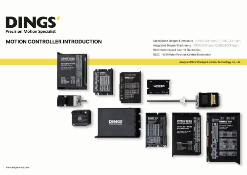
- Power Supply: The devices operate on DC power ranging from 12V to 72V, depending on the model.
- Output Current: Ranges from 0.1A to 6.5A per phase for stepper drivers and up to 20A peak for brushless servo drivers.
- Control Methods: Include pulse-direction, RS485, EtherCAT, CANopen, and analog speed control.
- Encoder Support: Incremental, ABS, and Sin/Cos encoders are supported, varying by model.
- Stepper Drivers: Support closed-loop control, microstepping, and various communication protocols (RS485, EtherCAT, CANopen).
- Brushless Servo Drivers: Support multiple motor types (DC, BLDC, PMSM, VCM) and protocols (CANopen, EtherCAT).
- Protection: Include motor short-circuit, undervoltage, overvoltage, and overcurrent protection.
- Operating Temperature: 0 to 50°C, with recommended driver temperatures under 60°C and motor temperatures under 80°C.
- Humidity: Less than 85% RH, no condensation.
- Installation: Devices should be installed in ventilated environments, vertically for natural cooling, with additional fans if necessary.
1. Brushless DC Motor: Power supply 12-48VDC, output current 6A (rated), 18A (peak), 3-phase PWM drive, analog speed control, RS485, digital hall sensor.
2. Integrated Stepper Electronics: Power supply 24-48VDC, output current 0.5-5.6A/phase, full-bridge bipolar PWM drive, CANopen, RS485, pulse-direction control.
3. DC Servo Motor: Rated voltage 48V, rated power 11-33W, high-resolution encoder, IP54 protection.
4. Outer Rotor Motor: Rated voltage 12-18V, rated power 4.1-63.5W, compact design, IP20 protection.
Procedures and Installation:
1. Ensure installation in a ventilated environment to aid heat dissipation.
2. Consider terminal size and cooling space during installation.
3. Install drivers vertically for natural cooling; add a fan if necessary.
Operating Environment:
1. Avoid dust, oil mist, and corrosive gas.
2. Maintain humidity below 85% RH, no condensation.
3. Temperature range: -15 to 50°C for brushless motors, 0 to 40°C for stepper motors.
Features and Recommendations:
1. Supports RS485 and MODBUS-RTU communication protocols.
2. High response, low vibration, and low noise for precise positioning applications.
3. Customization options available for various voltage requirements and environmental protections.
Contact Information:
For more information, contact DINGS’ representatives in China, USA, Europe, Korea, and Japan. Visit www.dingsmotion.com for further details.
Catalog excerpts
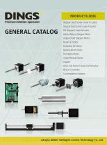
Precision Motion Specialist GENERAL CATALOG PRODUCTS 2025 Stepper Lead Screw Linear Actuator Stepper Ball Screw Linear Actuator PM Stepper Linear Actuator Hybrid Rotary Stepper Motor Hollow Shaft Stepper Motor Brush DC Motor Brushless DC Motor Slotless BLDC Motor Frameless Motor Linear Module Series Gripper Voice Coil Motor / Voice Coil Actuator Motion Controller Customization Options Jiangsu DINGS' Intelligent Control Technology Co., Ltd.
Open the catalog to page 1
Welcome to Jiangsu DINGS' Intelligent Control Technology Co., Ltd. Jiangsu DINGS' Intelligent Control Technology Co., Ltd (stock code: 873593) was established in April 2008 and is an innovative technology enterprise. It has been awarded the titles of "National High tech Enterprise" and "National Specialization, Precision, and Innovation". Titles such as "Little Giant Enterprise" and "Jiangsu Province Science and Technology Small and Medium sized Enterprise". Our main products include precision stepper motors, DC motors, PMSM motors for new energy vehicles, voice coil motors, lead/ball screw linear...
Open the catalog to page 2
Product Warranty Statement DINGS’ provides product quality certificates during shipping, and customers are to inspect product according to technical drawings and/or related requirements. DINGS’s product warranty period is 2 years, calculated from delivery date, and customers are to refer to the product manual for proper storage and usage of the product. During the service life or warranty period, if our products are damaged or do not work properly due to quality problems, DINGS’ provides no-charge repairs. The following conditions do not belong to the scope of free maintenance: 1. When the validity...
Open the catalog to page 3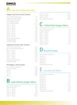
Precision Motion Specialist ^A Lead Screw Linear Actuator Stepper Lead Screw Linear Actuator Part number construction A-2 Lead screw code selection A-3 Product selection guide A-4 Stepper Ball Screw Linear Actuator Part number construction A - 5 9 Ball Screw lead code selection A -60 PM Stepper Linear Actuator Part number construction A - 8 1 B Hybrid Rotary Stepper Motor Part number construction B-2 C Hollow Shaft Stepper Motor Part number construction C- 2 Size 34 ■ 86 mm C-11 [D Brush DC Motor Part number construction D- 2 Part number construction E- 2
Open the catalog to page 4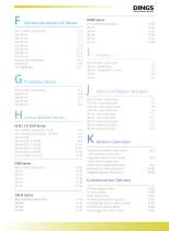
Precision Motion Specialist Slotless Brushless DC Motor Part number construction F- 2 Frameless Motor Part number construction H -4 9 Part number construction I- 2 Part number construction G- 2 H Linear Module Series Part number construction : DLM FI -3 Part number construction : L-R DLM H- 4 Part number construction H- 3 5 DSLM Series Part number construction H-44 Voice Coil Motor / Actuator Part number construction J-2 12.7 mm voice coil motor J-3 13.2 mm voice coil actuator J-4 25.4 mm voice coil motor J-5 30 mm voice coil motor J-7 38 mm voice coil motor J-11 40 mm voice coil actuator J-12...
Open the catalog to page 5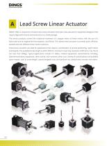
A Lead Screw Linear Actuator DINGS' offers a unique line of Lead Screw Linear Actuators that open new avenues for equipment designers that require high performance and endurance in a small package. The various products convert the rotational movement of a stepper motor to linear motion, with the use of a lead screw and an engineered thermoplastic nut (Delrin). This allows linear actuators to provide quiet, efficient, durable and cost effective linear motion solutions. These linear actuators are ideal for applications that require a combination of precise positioning, rapid motion and long life....
Open the catalog to page 6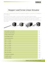
Precision Motion Specialist DINGS' Stepper Lead Screw Linear Actuators come in eight sizes, ranging from a square frame 14 mm (NEMA 6) to 86 mm (NEMA 34). There are four form factors available - External, Non-Captive, Electric Cylinder (Captive) and Kaptive. DINGS' provides over 20 different travels/step of lead screws ranging from 0.00006 inch [.0015mm] to 0.005 inch [.127mm]. Micro-stepping can be used for finer resolution and various step motor angle options are available. Max. 2,400N linear thrust force can be generated and brake / teflon coating / encoder / manual knob options also can be...
Open the catalog to page 7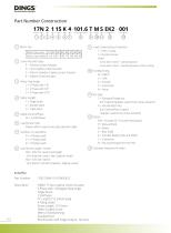
Precision Motion Specialist Part Number Construction (2) Linear Actuator Type E = External Linear Actuator N = Non-Captive Linear Actuator C = Electric Cylinder (Captive) Linear Actuator K = Kaptive Linear Actuator (3) Motor Step Angle (6) Lead Screw Code Please refer to lead screw code selection table (7) Number of Lead Wires (8) Lead Screw Length / Stroke XXX = XXX mm Lead screw length [For External Linear / Non-Captive Linear] [For Electric Cylinder (Captive) / Kaptive Linear] (9) Lead Screw Surface Treatment T = Teflon Coating S = Standard Grease [Note] -Screw lead <0.6mm : standard grease...
Open the catalog to page 8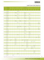
Lead Screw Code Selection Lead Code 1.8 degree motor travel per step inch (mm) Motor size (mm) 35 / 42 Screw Dia. inch (mm) Note : The data in [ ] refers to the conversion between metric and imperial systems. When the division is inco
Open the catalog to page 9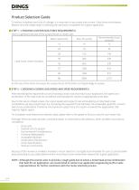
Precision Motion Specialist To reduce complexity and cost of a design, it is important to accurately size a motor / lead screw combination. Belows are a few simple steps in selecting the necessary compotents for a given application. Here is a general overview of the output thrust vs. motor size: As the size of the motor increases, the output thrust of the motor correspondingly increases. After estimating the required thrust and choosing a motor size that may fit your application, the speed and acceleration of the load must be considered and evaluated to choose an appropriate screw lead. Due to...
Open the catalog to page 10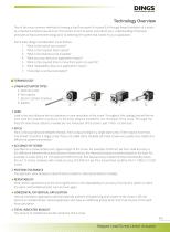
DINGS Precision Motion Specialist One of the most common methods of moving a load from point A to point B is through linear translation of a motor by a mechanical lead screw and nut. This section is here to assist and refresh your understanding of the basic principles of lead screw technology prior to selecting the system that is best for your application. Some basic design consideration are as follows: 1. What is the load of your system? 2. What is the required linear speed? 3. What is the distance to be travelled? 4. What accuracy does your application require? 5. What is the required time...
Open the catalog to page 11All Jiangsu DINGS’ Intelligent Control Technology Co. catalogs and technical brochures
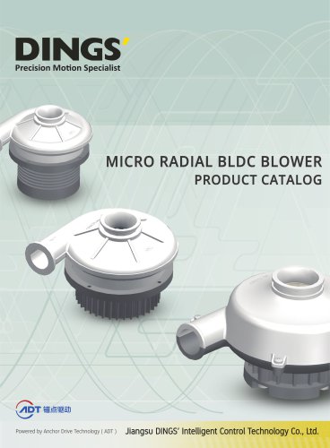 MICRO RADIAL BLDC BLOWER
82 Pages
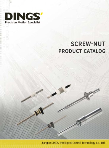 SCREW-NUT
48 Pages
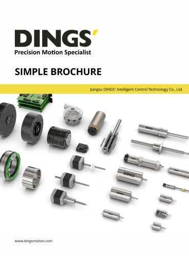 SIMPLE BROCHURE
8 Pages