- Catalogs
- JRI Orthopaedics
- ACE Surgical Technique
ACE Surgical Technique
1 /24Pages
ACE Surgical Technique
1 /24Pages
Catalog excerpts

HXLPE Ceramic Dual Mobility HXLPE Acetabular System Ceramic HXLPE Ceramic Dual Mobility HXLPE Ceramic OPERATIVE TECHNIQUE Dual Mobility Dual Mobility
Open the catalog to page 1
Contents Pre-operative Planning Acetabular Preparation Acetabular Trial Reduction Screw Fixation Liner Insertion - Polyethylene Liner Insertion - Ceramic Dual Mobility Trial Reduction Dual Mobility Definitive Sleeve Insertion Dual Mobility Definitive Femoral Head Assembly Dual Mobility Final Reduction ACE® Implants ACE® Instrumentation ACE® Bearing Combinations
Open the catalog to page 2
Pre-operative planning for the ACE® Acetabular Cup System is available on all commonly used 2D software and in acetate. To ensure accurate templating, Anterior / Posterior and Lateral radiographs will be required with neutral leg alignment and stable pelvic tilt to help determine the implant size and positioning required to restore the patient’s natural anatomy and hip biomechanics. Be sure that the cup is well centred within the acetabulum and at an abduction angle of approximately 45°, taking into account the subchondral bone and selecting a size that is located between the superior rim and...
Open the catalog to page 3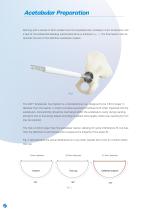
Acetabular Preparation Starting with a reamer 6-8mm smaller than the templated size, increase in 1mm increments until a bed of circumferential bleeding subchondral bone is achieved The final reamer size de- termines the size of the definitive acetabular implant. The ACE® Acetabular Cup System is a hemispherical cup, designed to be 1.8mm larger in diameter than the reamer, in order to achieve equatorial interference fit when impacted into the acetabulum. Concentricity should be maintained within the acetabulum cavity during reaming, aiming for line-to-line sizing. Adjust according to patient bone...
Open the catalog to page 4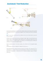
Acetabular Trial Reduction 45° Ensure that the acetabulum is clean and clear of debris, excise any soft tissues that may inhibit the seating of the cup. The trial cups are available in 2mm increments and mimic the definitive cup. NB: The screw holes in the trial cup are for reference only, do not use these holes to secure the trial cup in position. Securely screw the trial cup onto the cup impaction handle. Align the screw holes with the superior aspect of the acetabulum before attaching the cup alignment guide onto the cup impactor handle (Fig. 3). Patient position, with respect to the operating...
Open the catalog to page 5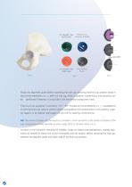
Neutral Liner 10° Hooded Liner (Ceramic & XLPE) (XLPE only) 20° Hooded Liner (XLPE only) Fig. 6 Unclip the alignment guide before impacting the trial cup, ensuring that the cup position stays in the correct orientation be With the trial cup firmly in position, a preliminary trial reduction can performed if desired, in conjunction with the femoral component trials. Trial liners are available in standard, +10°, +20° hooded and Dual Mobility on the trial liners are used to control rotation and position the hooded trials in the posterior-superior aspect, or as desired. See pages 22 and 23 for bearing...
Open the catalog to page 6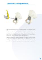
Select the same diameter definitive cup as the trial implant, and screw firmly onto the cup impactor handle. Recreate the position of the trial implants before attaching the cup alignment guide. Using the cup alignment guide, recreate the seating position of the trial cup. Impact the cup firmly ensuring the orientation of the cup is maintained. An audible change of tone and tactile feedback will indicate when the cup is fully seated (Fig. 9). The impactor handle can be removed and the seating of the cup checked, through the apical hole and/or through the screw holes. Should the cup be difficult...
Open the catalog to page 7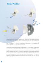
Screw Fixation Additional fixation can be achieved with the use of cancellous bone screws to supplement primary mechanical fixation. Each screw hole comes fitted with a screw cap to stop wear particle migration into the acetabular bone. Apart from the cups optimised for large bore cups, these can be removed with the 3.5mm hex screwdriver. A drill guide is placed carefully in the chosen screw hole, ensuring that it is fully seated (Fig. 11). A pilot hole is made using the disposable drill bit of the appropriate size (see page 19), which can be used with power or manually. The length of the screw...
Open the catalog to page 8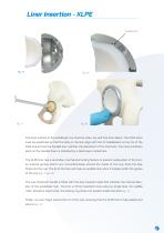
Liner Insertion - XLPE Audible click The inner surface of the acetabular cup must be clean, dry and free from debris. The XLPE liners must be positioned so that the tabs on the liner align with the 12 castellations on the rim of the shell. Ensure that the hooded liner matches the placement of the trial liners. The most prominent point on the hooded liners is indicated by a black laser-marked line. The XLPE liner has a secondary mechanical locking feature to prevent subluxation of the liner; an internal groove which runs circumferentially around the inside of the cup. Push the liner firmly into...
Open the catalog to page 9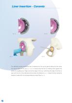
Liner Insertion - Ceramic The definitive ceramic acetabular liner is inserted into the cup by gently sliding the liner down the internal taper of the cup Ensure that the liner is uniformly flush against the entire rim by gliding your finger around the edge of the cup, confirming the edge of the liner is even with the rim of the shell around the whole circumference (Fig. 21). Impact the liner using the impactor handle with the corresponding size head fitted (Fig. 22).
Open the catalog to page 10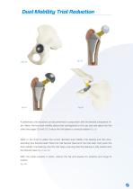
Dual Mobility Trial Reduction A preliminary trial reduction can be performed in conjunction with the femoral component trials. Select the trial dual mobility sleeve that corresponds to the cup size and place into the shell (see pages 22 and 23). Ensure the trial sleeve is correctly seated (Fig. 23). Refer to the chart to select the correct diameter dual mobility trial bearing and the corresponding trial femoral head. Place the trial femoral head onto the trial stem, then push the dual mobility trial bearing onto the trial head, ensuring that the bearing is fully seated onto the femoral head (Fig....
Open the catalog to page 11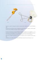
Should you need to change the trials to achieve better stability, lever the Dual Mobility (DM) bearing off the trial femoral head, and replace the femoral head with a longer or shorter length until the correct stability and range of motion is achieved. Should the trial bearing and head be difficult to separate, a separator tool is available (Fig. 27). To exchange the Femoral Head (FH) for a longer or shorter trial head, use the DM/FH separator tool by clamping the DM bearing firmly and levering the FH out of the DM bearing. Retain the trial DM/FH assembly for use in trial reduction with the definitive...
Open the catalog to page 12All JRI Orthopaedics catalogs and technical brochures
 Avanteon Surgical Technique
24 Pages
 Product Catalogue
8 Pages
 CSF Plus Surgical Technique
20 Pages
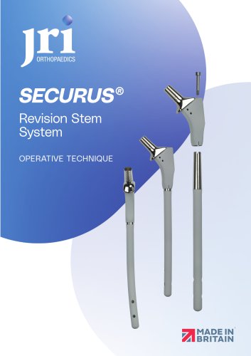 Securus Surgical Technique
40 Pages
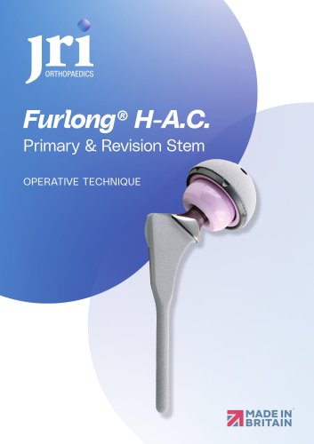 Furlong H-A.C Surgical technique
24 Pages
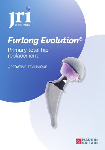
 Furlong
20 Pages
- Femoral stem
- Acetabular prosthesis
- Cementless femoral stem
- Cementless acetabular prosthesis
- Hip prosthesis
- Cemented femoral stem
- Femoral head prosthesis
- Primary hip prosthesis
- Revision femoral stem
- Cementless hip prosthesis
- Shoulder prosthesis
- Revision shoulder prosthesis
- Cemented hip prosthesis
- Minimally invasive femoral stem