Catalog excerpts

Tragabilile, surveillance et metrologie JRI, Sociele par actions simplifiee au capital de 4 000 000 € Pole logistique / 2 Rue de la Voivre / PA Technoland / BP 21 / 25490 FESCHES LE CHATEL / France Siege Social: 16 Rue Louis Rameau / CS 90050 / 95872 BEZONS Cede* / Franca / APE 2651B / TVA FR 02 3S0 332 S58
Open the catalog to page 1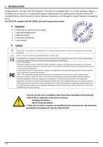
I. INTRODUCTION Congratulations, you own a SPY RF N (Digital) ! This device is equipped with 1 or 2 inputs (analog or logical…). It enables you to record 1 or 2 physical parameter (depending on the model) and to transfer wireless the recorded data by radio frequency to Sirius software installed on a PC through to a Spy RF Modem managed by Sirius. The SPY RF N complies with EN 12830, only with temperature probes. a) 1 SPY RF N1 (1 input) or U2 (2 inputs) 1 wall-mounting bracket 1 adhesive plaster 1 connector protection 1 user manual Symbols RECYCLING : do not throw in a rubbish dump or in a...
Open the catalog to page 3
II. INSTALLATION RECOMMENDATIONS The Spy RF is a recorder of physical parameters able to communicate in radiofrequency with the operating software SIRIUS thanks to a Spy RF ModeM. . To guarantee optimal radio transmission, it must meet a number of recommendations, as any wireless transmission is subject to disturbances a) Perturbations sources Presence of obstacles in the way of the waves between the Spy RF ModeM and the Spy Rf (wall, ceiling, person, furniture…) or close to the antenna. Obstacles thickness in the way of the waves. The absorption is more important in diagonal as...
Open the catalog to page 4
Wall-mounting bracket Waiting mode Memory status Radio signal Full memory. You must transfer the data into your PC. Low battery. You must change the battery (See "battery change p22) The SPY RF N is equipped with rapid connectors which make the installation of different type of probes very easy. The probes can otherwise be disconnected from the recorder to be changed or to change the recorder
Open the catalog to page 5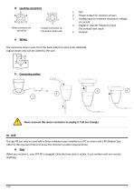
Female connector on the probe cable (side N/C Power output for resistive sensors Analog input to measure resistance, voltage or current Digital or counter frequency input Dry contact start input Ground The connector view is seen from the back (side from pins to be soldered). Logical inputs only can be cabled by the user. Connecting probes Never unscrew the sensor connector to unplug it. Pull out strongly. IV. USE The Spy RF can only be used with a Sirius software issue installed on a PC or server and a RF Modem Spy. (refer to the manual of Sirius to know the minimum system requirements) a)...
Open the catalog to page 6
To start your SPY RF, please press between 5 and 10” on the button: the 2 LEDs are on and flash at the same time - all the display segments are also on - SPY RF is now in waiting mode Remark: If you press >10’’ => no effect => remains off Waiting mode The SPY RF is ready to receive a configuration or to start a new recording session. The symbol “Halt” is on: no measures in progress. Use the pushbutton to start. d) Configuration SPY RF configuration is done from the Sirius software (see Sirius user manual) and then transferred into your SPY RF by radio frequency thanks to a Spy RF ModeM....
Open the catalog to page 7
• at a programmed date and time: by the change of a logic input (on channel 2) then flashes every 1 minute Manual start Press shortly on the pushbutton then flashes every 1 minute It displays the temperature in °C degrees, channel number, measurement unit and memory The green LED flashes every minute. Alarm visualisation The SPY RF is equipped with different alarm indicators, when a threshold limit is overpassed. Threshold indicator Value measured
Open the catalog to page 8
Measurement stop Depending on the configuration, the SPY RF can stop recording or not. The different options are: Rolling memory: once the memory is full, the new values replace the old ones. Full memory: the recorder stops when its memory is full. With the software: you can put the SPY RF in standby mode with Sirius when you do not use your recorder. With the pushbutton: this option is valid only if the SPY RF is configured in transport mode with a start by pushbutton. To stop your SPY RF, press between 5 and 10” on the button: - The 2 LEDs are on and then flash alternatively. - The screen...
Open the catalog to page 9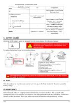
Device set up in transportation mode Pushbutton pressing The 2 leds are on and flash at the same time. Green led 2" = beginning of measurements Mode Off Starting measurements Pushbutton The 2 leds are on and flash at the same time = Waiting for Delayed (date & time) starting measurements Immediately The 2 LEDs are on and then flash alternatively = ending measurements Mesure The 2 LEDs are on and then flash alternatively = ending measurements V. BATTERY CHANGE When the SPY RF battery has to be replaced, the LCD screen displays the following message: DOWNLOAD THE MEMORY BEFORE CHANGING THE...
Open the catalog to page 10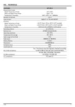
VIII. TECHNICALS FEATURES Measurement range Digital Temperature Probe Deep Low Digital Temp Probe Temperature / Humidity Number of channels Type of input Accuracy Digital Temperature Probe Deep Low Digital Temp Probe Temperature / Humidity Recording interval Memory size Operating conditions Temperature for storage Radio range (in free field) Radio band Battery lifetime Dimensions Protection level Classification IK EN 12 830 compliance CE ERM compliance FCC compliance Yes : This device must be regularly checked according to EN 13 486 (1 time per year recommended) EN 301 489 / EN 61000 / EN...
Open the catalog to page 11
IX. CAPACITY OF OPERATION DATA SHEET JULES RICHARD INSTRUMENTS Fiche d'aptitude a I'emploi selon la norme NF EN12830 Capacity of operation compliant to EN12830 Modele Imodel: Type de materiel / equipment type : Utilisation / application : Classe de precision / accuracy class: enregistreur de temperature / temperature recorder stockage / storage Tableaux des essais / Test table Pour Jules Richard Instruments Le Directeur Technique et Qualite : Technical and quality manager -
Open the catalog to page 12
X. WARRANTY JRI products carry a one year warranty and guarantee against defects in their components or workmanship. During this period if any product supplied by the Company proves on inspection to be defective, the Company will at its own option replace the same or refund to the Buyer the price of the product. In no circumstances will JRI' liability exceed the price of the product paid by the buyer or the cost of replacement. JRI shall not in any event be liable to the Buyer for any indirect or consequential loss or damage costs or expenses whatsoever which might arise out of or in...
Open the catalog to page 13All JRI catalogs and technical brochures
-
 LoRa® SPY T0
1 Pages
-
 LoRa® SPY T1
1 Pages
-
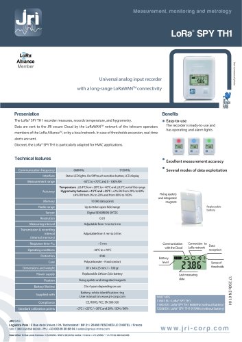 LoRa® SPY TH1
1 Pages
-
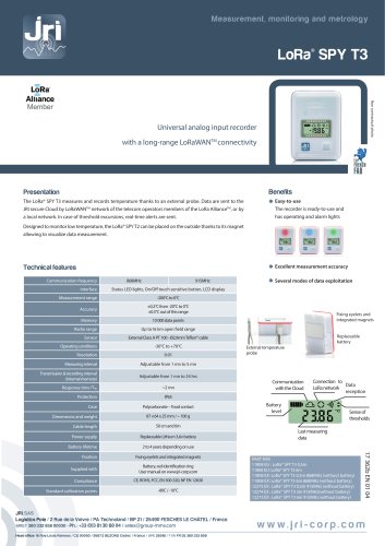 LoRa® SPY T3
1 Pages
-
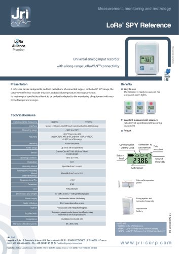 LoRa® SPY Reference
1 Pages
-
 BLOODTEMP 10
1 Pages
-
 FREEZE INDICATOR 0°C
1 Pages
-
 SPY IP
2 Pages
-
 SPY RF® AIR
2 Pages
-
 SPY RF® ReferencE
11 Pages
-
 Mini SPY RF Green
2 Pages
-
 SPY RF® TC
11 Pages
-
 SPY RF® U
13 Pages
-
 SPY RF® T+
10 Pages
-
 SPY USB MULTI USE
2 Pages
-
 SPY USB SINGLE USE
2 Pages
-
 MobiTemp
2 Pages
-
 SiriusWeb
2 Pages