- Catalogs
- Kendrion Kuhnke Automation
- Catalogue Rotary Solenoids


Catalogue Rotary Solenoids

Catalogue Rotary Solenoids
A rotary solenoid is a device that uses rotary motion from a neutral position when energized. It can be single acting or reversing, with the latter having no neutral position and moving between two end positions.
Torque is calculated by the force generated in the direction of motion, considering friction loss, multiplied by the length of the actuating arm. Starting torque is measured at the start position, and end torque is measured 5° before the end position.
Threaded holes are provided for fixing. Care should be taken to avoid damaging the winding by forced tightening or boring out holes. External stops are recommended to increase the life expectancy of the solenoids. Enhanced cooling allows for a higher duty cycle.
The rotary solenoid has an armature that moves between two internal stops. When energized, the armature rotates to close the air gap until an end stop is reached. Return action can be achieved by a spring or a second solenoid.
Standard solenoids have angular travels of 25°, 35°, 45°, 65°, or 95°, with a manufacturing tolerance of +3°.
Actuation time depends on the angle of rotation and duty cycle. It is influenced by resisting torque and inertia of coupled parts.
The document includes a detailed diagram of a rotary solenoid, showing components like the return spring, ball bearings, and casing.
Rotary solenoids are available in various designs, with options for direction of rotation, centering shoulder, and return spring configuration.
Rotary solenoids are used in sorting mechanisms, counting devices, throttle valves, and more. They are suitable for transport systems due to their insensitivity to linear acceleration.
Series D and E solenoids are available in circular and square designs, respectively, with various sizes and rotary strokes. They offer high output with minimal space requirements. Custom specifications can be accommodated based on quantity.
The document provides a detailed technical description of rotary solenoids, specifically focusing on the D, E, and UD series. These solenoids are designed for applications requiring precise swivel actions with fixed angles of rotation, making them suitable for modern automation systems.
Rotary solenoids are available with tapped mounting holes on both surfaces, and variations can be customized to meet specific customer requirements. The two-directional rotary solenoids (UD series) consist of two solenoids coupled in tandem, eliminating the need for a return spring, thus enhancing efficiency.
The solenoids are designed to operate at 24 V DC with a 100% duty cycle. They can be operated at higher voltages using an adjustable voltage source to achieve the required power, but caution is advised to prevent overheating. The maximum operating time is limited to 5 minutes to avoid thermal damage.
Custom solenoids can be manufactured cost-effectively based on order quantities. Preferred types are always in stock for quick delivery, typically within a week, subject to current order levels.
The document includes detailed specifications such as initial and end torque values, nominal resistance, and current ratings for various solenoid sizes and configurations. It also provides guidelines for calculating the required power and duty cycle based on coil current measurements.
On request, solenoids can be supplied with 2 RS bearings, although this reduces the initial torque by approximately 10%. Solenoids with a rotary angle of 95 degrees should not be equipped with these bearings. The document also mentions the availability of solenoids with adjustable return springs for specific models.
The solenoids are tested at a voltage of 2500 V (eff) for thermal stability, with a maximum permissible temperature of 130°C. Accessories such as plug-in sockets are available for specific connection types.
Catalog excerpts

Magnete Solenoids
Open the catalog to page 1
Diese Produkte entsprechen der Niederspannungsrichtlinie 2014/35/EU. Die Einhaltung der EMV-Richtlinie 2014/30/EU ist mit entsprechenden Schaltgeräten bzw-. Ansteuerungen vom Anwender sicherzustellen. These products comply with low voltage regulations 2014/35/EU. The user must ensure that EMC regulation 2014/30/EU is complied with using the appropriate switching devices or drivers respectively. Dieser Katalog ist vor allem für den Konstrukteur, Projekteur und Geräteentwickler bestimmt. Er gibt keine Auskunft über Liefermöglichkeiten. Die angegebenen Daten dienen allein der Produktbeschreibung...
Open the catalog to page 2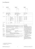
Linearbewegung stoBen, ziehen Drehbewegung schwenken Haftaufgabe festhalten Einfach-, Umkehr-, Bistabil- abhangig von Hub, Anfangs-, Endkraft, Einschaltdauer Hub Anfangs- Typ Einfach-, Umkehrwirkend abhangig von Drehwinkel, Anfangs-, Endmoment, Einschaltdauer* Winkel Anfangs- Typ moment** Einfach-, Permanent-abhangig von Haltekraft - bistabil - permanent Stellzeit/ Lebensdauer Preis/Leistung Modifikation - Magnetkraft, Hub - Ruckstellkraft - Kraftabnahme - Befestigung - Spule, Erregung Umgebungs-temperatur - Oberflachenschutz - Neuentwicklungen Kleine Magnete erreichen im allgemeinen die kurzere...
Open the catalog to page 3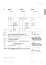
linear movement pull/thrust stroke < 35 mm yes no rotary movement shift angle of rotation < 95° yes no latching task hold force < 1400 N yes no - bistable - permanent adjusting time/ service life price/performance modifications - solenoid force, stroke - return force/stroke - output shaft - fixing - coil excitation, ambient temperature - surface protection - new developments single, two-directional, bistable depend on stroke, initial force, end force, duty cycle* stroke initial series single, two-directional depend on angle of rotation, initial torque, end torque, duty cycle* angle...
Open the catalog to page 4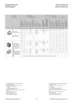
Solenoid Survey Rotary Solenoids Drehmagnete fur hochste Anforderungen Rotary solenoids for highest workload Magnetubersicht Drehmagnete Magnet-Typ Solenoid type E Drehmagnete in ver-gossener Ausfuhrung fur hochste Anforderungen Rotary solenoids with square cross section for highest workload UD Umkehr-Drehmagnete fur Standardanwendungen Twodiredional rotary solenoids for standard purposes DS 1! Alle Einfach-Drehmagnete sind in rechter oder linker Drehrichtung lieferbar. 2) Min. ED bedeutet bei der kleinsten im Katalog angegebenen Einschaltdauer. 3) F = Litze M = Steckhulsenanschluss 2,8 mm N...
Open the catalog to page 5
Solenoid Survey Linear and rotary solenoidsAccessories Bestell-Nr./ Order-No. KUHNKE Magnetkatalog 03/17 10 KUHNKE Solenoi
Open the catalog to page 6
Drehmagnete D, E, UD Rotary Solenoids Series D, E, UD
Open the catalog to page 7
Register Rotary Solenoids Seite Page Technische Informationen fur Drehmagnete 1. Begrifferklarungen 1.1 Drehmagnete 1.2 Mechanische Begriffe 2. Montagehinweise 3. Drehmomentabnahme an der Welle 4. Funktionsbeschreibung 5. Drehwinkel 6. Anzugszeit 7. Detaildarstellung eines Drehmagneten D 8. Wellenausfuhrungen 9. Anwendungsbeispiele Drehmagnete Technische Beschreibung/Vorzugstypen Typ D und E einfachwirkend, Typ UD umkehrwirkend Drehmagnete nach Kundenspezifikation Vorzugstypen Typ D Typ E Typ UD Zubehor Typen D, E und UD Technical Notes on Rotary Solenoids 1. Definitions 1.1 Rotary solenoids 1.2...
Open the catalog to page 8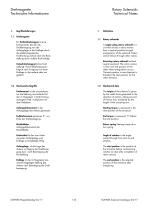
Rotary Solenoids Technical Notes Drehmagnete Technische Informationen1. Begriffserklarungen 1.1 Drehmagnete Ein Einfachdrehmagnet ist eine Komponente, bei der die Drehbewegung von der Anfangslage in die Endlage durch die elektromagnetische Kraftwirkung und bei dem die Ruck-stellung durch auBere Kraft erfolgt. Umkehrdrehmagnet (ohne Null-stellung). Die Drehbewegung erfolgt je nach Erregung von einer Endlage in die andere oder um-gekehrt. 1.2 Mechanische Begriffe Drehmoment ist der ausnutzbare, um die Reibung verminderte Teil der im Magneten in Drehrichtung erzeugten Kraft, multipliziert mit dem...
Open the catalog to page 9
Drehmagnete Technische Informationen Rotary Solenoids Technical Notes Montagehinweise Für die Befestigung sind zwei bzw. drei Gewindelöcher auf beiden Stirnseiten vorgesehen (siehe Maßbilder). – Bei der Auswahl der Befestigungsschrauben ist die in den Maßbildern angegebene Gewindetiefe zu berücksichtigen. Gewaltsames Hineindrehen der Schrauben sowie Aufbohren der Befestigungslöcher führt zu Beschädigung der Wicklung. – Schläge auf die kugelgelagerte Welle sind zu vermeiden. – Um die Lebensdauer der Drehmagnete zu erhöhen, empfehlen wir, zusätzliche Massenkräfte von den internen Anschlägen der...
Open the catalog to page 10
Rotary Solenoids Technical Notes Drehmagnete Technische Informationen 4. Funktionsbeschreibung Der Drehmagnet besitzt einen Dreh-anker, der auf einer beiderseitig gelagerten Welle befestigt ist und zwischen zwei internen Anschlagen eine winkelbegrenzte Drehbewegung ausfuhrt. Anker und Kern sind z. B. mit schrag zur Ankerwelle liegenden Stirnflachen versehen, zwischen denen sich der Arbeitsluftspalt befindet. Wird die Magnetspule erregt, hat der Drehanker das Bestreben, den Arbeitsluftspalt zu verringern, d. h. der Anker dreht sich bis zum Erreichen der Anschlage. Die Ruckstellung des Ankers kann...
Open the catalog to page 11
Rotary Solenoids Technical Notes Drehmagnete Technische Informationen 6. Anzugszeit Typische Anzugszeiten unserer Drehmagnete in Abhangigkeit vom Drehwinkel sowie der relativen Einschaltdauer finden Sie in der nachstehenden Ubersicht. Typische Anzugszeiten bei unbelasteten Drehmagneten 6. Actuation time Typical relationships between the actuation time, angle of rotation and relative duty cycle for our rotary solenoids are given in the following extracts. Typical actuation times for unloaded rotary solenoids Bei belasteten Magneten wird die Anzugszeit sehr stark vom Gegen-drehmoment (einschlieBlich Reibungsmoment)...
Open the catalog to page 12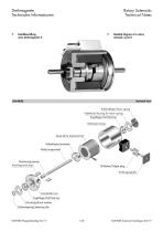
Drehmagnete Technische Informationen Rotary Solenoids Technical Notes Detaildarstellung eines Drehmagneten D Detailed diagram of a rotary solenoid, series D Sectional view Rückholfeder/return spring Federkorb/housing for return spring Kugellager/ball bearing Gehäuse/casing Spule (ohne Isolation)/coil Ankerkörper/armature Welle/output-shaft Distanzring/spacer Anschlag/end stops N-Stecker/N-type plug Dichtung/gasket Kernplatte/core Kugellager/ball bearing Druckring/thrust washer Sicherungsring/retaining clip KUHNKE Solenoid Catalogue 03/17
Open the catalog to page 13All Kendrion Kuhnke Automation catalogs and technical brochures
 Solenoid Valve Type 63.1
2 Pages
 Proportional Valve Type 68P
2 Pages
 Solenoid Valve Type 63.0
2 Pages
 Motorized Door Lock HS7722
2 Pages
 Fluid Isolation Valve
2 Pages
 Catalogue Holding Solenoids
16 Pages
 Kuhnke Sub Plate Technology
5 Pages
 High-Performance Valve 798
2 Pages
 10 mm oxygen valve
1 Page