

ClarityChrom® Version 8.7

ClarityChrom® Version 8.7
- Intended Use: ClarityChrom® software is designed for chromatographic data acquisition and analysis, supporting KNAUER HPLC systems and other devices with digital interfaces. It can control up to four chromatographs simultaneously.
- Supported Instruments: Compatible with a wide range of KNAUER instruments, including detectors, pumps, autosamplers, and fraction collectors.
- Measuring: Supports simultaneous data acquisition from up to four chromatographs, each capable of using up to 12 detectors.
- Integration and Overlay: Offers extensive chromatogram modification capabilities and simultaneous display of multiple chromatograms.
- Calibration: Provides internal and external standard calculation methods and calibration of peak groups.
- Extensions: Integrates workflows with GPC calculations, PDA data processing, and more.
- Automated Measuring Support: Allows creation of sequence tables for sample sets.
- Postrun and Summary Result Tables: Automatically handles post-measurement tasks and displays selected results.
- User Settings and Export/Import: Offers customizable display settings and supports various export/import formats.
- LIMS Connectivity: Facilitates sample submission and result output via ASCII transfers.
- Method and Calibration History: Allows easy display of chromatograms under original conditions.
- Batch Processing and User Calculations: Supports batch processing and custom calculations.
- User Accounts and Audit Trail: Manages access rights and records operations.
- Electronic Signature and Networked Solution: Supports electronic signatures and network access to files.
- Language Localizations: Available in multiple languages, with some menus only in English.
- Fraction Collection: Supports various fractionation methods and solvent recycling.
- LC/GC/AS/MS Control: Includes add-ons for controlling chromatographs and mass spectrometers.
- Demo and Trial Versions: Offers a free demo version and a trial version with full options for a limited time.
The ClarityChrom® workstation is compatible with Windows 11, 10, 8.1, and 7 SP1, supporting both 32- and 64-bit versions. Minimum hardware requirements include a Pentium 2000 MHz CPU, 4 GB RAM, and 80 GB of free disk space, with an SSD recommended over an HDD. A USB port is necessary for the license dongle, and a DVD-ROM drive is required for installation. The recommended monitor resolution is 1280 × 1024 or 1680 × 1050 with 64 K colors.
The installation process requires a local administrator account and should be performed after installing any pending Windows updates. The installation involves inserting the ClarityChrom® DVD, following on-screen prompts, and ensuring the USB license dongle is not connected until after installation. The software suggests default installation paths, which should be accepted unless specific requirements dictate otherwise. The installation includes Microsoft Visual C++ redistributable and may require additional driver installations.
Upgrades are full versions and require the complete uninstallation of previous software versions. It is recommended to back up all data before upgrading, as the new version uses a different data format incompatible with older versions.
The ClarityChrom® software features a hierarchical structure with a main window for configuration and user management. The instrument window allows for data acquisition and manipulation, supporting up to four independent instrument windows. The chromatogram window is central for displaying and evaluating chromatograms, while the calibration window is used for managing calibration curves. The sequence window facilitates the sequential measurement of multiple samples, supporting both active and passive operations.
The method setup dialog in ClarityChrom® software allows users to configure measurement and evaluation settings, which are saved in a template method file. This setup is accessible via the method setup icon in the instrument window. Detailed setup instructions for KNAUER devices are provided in chapter 8.
This section provides a model analysis to demonstrate basic procedures with the ClarityChrom® station. The software allows immediate measurement without extensive preparation, provided the system is configured. Users can start the program via the desktop icon or through the start menu, and initiate analysis by clicking SINGLE ANALYSIS.
Users can monitor signals from detectors for drift and noise in the data acquisition window. Measurement parameters such as voltage range and sampling rate must be set before analysis, as changes during measurement invalidate results.
The SINGLE ANALYSIS dialog allows users to enter analysis titles and run analyses. During the run, the status bar displays the current measurement time. Data acquisition can be controlled using icons for single run, sequence run, resume sequence, stop, and abort. Chromatograms can be compared to background or subtracted chromatograms.
Completed analyses are displayed in the chromatogram window if the "OPEN CHROMATOGRAM WINDOWS" option is selected. Users can zoom into sections of the chromatogram for detailed evaluation.
Calibration curves are an extensive part of the ClarityChrom® station, saved in separate files with up to twenty concentration levels. Calibration files are linked to chromatograms for result calculation.
Mobile Control's monitor mode is no longer supported. Ensure Mobile Control is closed before starting ClarityChrom®.
Configuration involves setting up necessary devices, which appear in the System Configuration window. Devices must be configured separately, with serial numbers entered for completion. Communication ports (RS-232 or LAN) must be defined, with functionality potentially limited by port choice.
HPLC systems can be set up in a LAN, requiring IPv4 addresses and specific IP ports. Configuration involves checking LAN properties, connecting devices, and configuring routers. Troubleshooting steps are provided for connection issues.
Configuration data for KNAUER devices can be downloaded to avoid manual entry errors. Devices connected via RS-232 or LAN can be selected for configuration data download.
ClarityChrom® software supports various KNAUER pumps, including AZURA® models P 8.1L, P 6.1L, and P 2.1L, among others. When configuring these pumps, it is crucial to select the correct interface that matches the software settings. Notably, the isobar mode for pump P 2.1L and the constant pressure mode for pump P 6.1L are unsupported. For pumps with RFID capabilities, an asterisk indicates a default pressure value.
Each device must have a unique name within the configuration to avoid conflicts. The serial port on the PC must be correctly selected to ensure error-free operation. Specific settings are required for different models, such as RS-232 for certain pumps and NET BAUD RATE 9600 for others.
For network-controlled pumps, the software can automatically recognize devices using their serial numbers. Static IP addresses can be set but require manual configuration in both the software and the pump.
The gradient mode must be correctly set in both the software and the pump. For LPG systems, the number of solvent components and cycle time must be configured accurately to prevent damage to LPG valves.
Pumps can be configured as auxiliary pumps for specific tasks, and settings like leak sensor sensitivity can be adjusted. Additional information about the pump can be entered for documentation purposes.
Several KNAUER RI detectors are supported, with configuration procedures being nearly identical across models.
- Name: Automatically suggested based on detector type. Ensure uniqueness within the instrument configuration.
- Serial Number: Enter the detector's serial number.
- Channel Name (RID 2.1L only): Option to enter a descriptive name for the channel.
- Signal Inversion (RID 2.1L only): Option to invert data for acquisition channels to avoid negative peaks.
- Serial Port: Select the PC's serial port connected to the detector.
- Y-Axis Units: Choose units for chromatogram display; µRIU for RI detectors.
- IP Address (RID 2.1L only): Automatically recognized if the device is connected and switched on. Static IP setup requires manual configuration.
- IP Port: Use port 10001 for KNAUER devices.
- Use S/N to Identify Instrument: Recommended to avoid IP address changes upon reset.
- Detector Type (WellChrom RI detectors only): Select from K-2300, K-2301, K-2400, K-2401.
- Leak Sensor Sensitivity (RID 2.1L only): Options include OFF, LOW, MEDIUM, HIGH.
- Additional Info: Enter extra information about the detector.
- Supported Models: AZURA® MWD 2.1L, UVD 2.1L, UVD 2.1S, WellChrom K-2000, K-2001, K-2500, K-2501, Smartline 200, 2500, 2520.
- Channel Configuration (MWD 2.1L only): Select 1-8 channels for data acquisition. Changes require device removal and re-addition.
- Signal Inversion: Available for channels 1-8 to handle negative peaks.
- Serial Port: Select the PC's serial port for detector connection. Note data rate limitations for certain models.
- IP Address and Port: Similar setup as RID 2.1L, with emphasis on using S/N for identification.
- Lamp Selection (UVD 2.1L, S 2520 only): Choose between D2 and halogen lamps.
- Shutter Control: Protects fiber optics by opening shutter only before runs.
- Leak Sensor Sensitivity: Options include OFF, LOW, MEDIUM, HIGH.
- Y-Axis Units: Options include AU, mAU, µAU for UV detectors.
- Flow Cell Description: Enter details for printing with instrument configuration.
- Supported Models: K-2600, S 2550, S 2600.
- Channel Configuration: Select 1-4 channels. Higher data rates require LAN connection.
- Signal Inversion: Available for channels 1-4 to handle negative peaks.
- Y-Axis Units: Only mAU is possible for diode array detectors.
- IP Address and Port: Similar setup as other models, with emphasis on using S/N for identification.
- Interface Selection: Choose the appropriate serial port for connection.
- Lamp Selection: Options for D2 and halogen lamps, specific to model capabilities.
- Shutter Control (S 2600 only): Protects fiber optics and optimizes data point integration.
- 3D Data Acquisition: Requires additional PDA license for full spectral functionality.
The document outlines the configuration process for KNAUER PDA detectors, including models like AZURA DAD 6.1L, DAD 2.1L, and others. It specifies that up to two detectors with 3D functionality can be used per system, with certain models requiring a 32-bit Windows version for operation. The configuration involves setting a unique detector name, serial number, and selecting channels for data acquisition. The document emphasizes using the serial number for device identification to avoid IP address conflicts.
The document details the setup for Shimadzu fluorescence detectors RF-10Axl and RF-20A/Axs, highlighting the need for firmware version 0.90 for the latter. It explains the limitations in functionality and the importance of matching COM port settings between the detector and software. The process for switching the detector to serial mode is also described.
Instructions are provided for configuring conductivity monitors like Smartline 2900 and AZURA CM 2.1S. The document advises using the serial number for device identification and provides details on setting up the IP address and port for communication. It also covers the acquisition of pH signals and the description of flow cells.
The document recommends using the serial number for device identification to prevent issues with dynamic IP addresses. It also advises on the use of specific lamps and shutter control settings for optimal detector performance.
A virtual detector is a software-based device that can acquire data from various sources, allowing for the recreation of chromatograms and the display of multiple detector traces in one chromatogram. It does not require a physical interface and can be used for triggering methods via external signals. Users can assign a unique name to the virtual detector and specify the y-axis units for signal display.
KNAUER provides A/D converters for controlling devices or acquiring data from unsupported devices. The Manager 5000/5050 and various interface boxes (IFU 2.1, IFU 2.1 LAN, IF2, KNAUER HPLC box) are used for integrating devices into the system. The configuration process involves selecting the appropriate serial port or interface, entering the serial number, and setting the voltage range for analog inputs. The KNAUER HPLC box has specific limitations on serial number storage and voltage range settings.
Each KNAUER interface device can support up to four channels, each configurable with unique names and settings. Channels can be used for data acquisition or auxiliary purposes, with options to set y-axis units, multipliers, and offsets. The analog output can control devices like pumps and detectors, with specific modes for each. The configuration ensures that channels are assigned correctly and that analog input and output are not used simultaneously.
- Unique naming is required for all devices and channels within the system.
- Serial numbers must be correctly entered, considering device-specific storage limitations.
- High sampling rate modes limit channel usage and disable certain features.
- Proper configuration of voltage ranges and conversion factors is crucial for accurate data acquisition and device control.
- Devices: Includes models like AS 3950, AZURA® Autosampler AS 6.1L, Spark Marathon, Spark Midas, and PLATINblue AS-1.
- Interface Setup: Recommends setting the DIP switch for serial interfaces to OFF to prevent communication issues. Autosamplers can be controlled via LAN if using TCP/IP protocol.
- Device Identification: Suggests using the serial number (S/N) for device identification over IP addresses to avoid issues with dynamic IP allocation.
- Specific Instructions: Detailed steps for setting devices to serial mode and accessing them via software are provided.
- Supported Models: CT 2.1, PLATINblue T-1, Smartline 4050, and Jetstream.
- Interface Options: Can be controlled via RS-232 or LAN, with recommendations to use S/N for identification.
- Additional Features: Includes settings for leak sensor sensitivity and valve configurations.
- Valve Grouping: Up to 8 valves can be configured as a group for streamlined programming.
- Supported Models: KNAUER WellChrom, Smartline, and AZURA® series.
- Configuration Details: Instructions for setting valve types, positions, and ports, with emphasis on unique naming conventions to avoid conflicts.
- Software Integration: ClarityChrom® includes a fractionation option from the original manufacturer.
- Use serial numbers for device identification to prevent issues with IP address changes.
- Ensure unique naming for devices within the configuration to avoid conflicts.
- Follow specific procedures for setting devices to serial mode before software access.
- Name: Assign a unique name to each fraction collector.
- Serial Number: Enter the serial number of the collector.
- Rack Type: Select the appropriate rack type from the drop-down list, ensuring it matches the collector's setup.
- Number of Vials: Automatically displayed based on rack type.
- Vial Volume: Set correctly to prevent overflow; can be overwritten if necessary.
- Serial Port: Choose the correct serial port on the PC; LAN interface is not supported.
- Baud Rate: Maintain the preset rate of 19200 baud for stable communication.
- Name: Assign a unique name.
- Model Selection: Choose between Vario 4000 and Vario 4000 Plus.
- Rack Type: Select from supported types; mixed configurations are not supported.
- Vial Volume: Ensure it matches the fractionation vials to prevent overflow.
- Serial Port: Select the appropriate port; supports RS-232 and LAN via DHCP or fixed IP.
- Baud Rate: Keep the preset rate of 9600 baud.
- Name: Assign a unique name.
- Serial Number: Enter the serial number.
- Rack Type: Ensure it matches the collector's setup.
- Vial Volume: Set correctly to prevent overflow.
- Serial Port: Choose the correct port on the PC.
The document provides instructions for configuring systems and devices using ClarityChrom® Software. It highlights that if only one device with digital outputs is included, the instrument selection will not be shown. Users can select the desired device to open the digital output dialog window.
This section describes the commands of the Instrument window, which is essential for chromatogram measurement and evaluation. Up to four Instrument windows can be displayed simultaneously, even if the number exceeds the licenses available. Unconfigured instruments can be used for offline data analysis, but methods cannot be created or changed unless the devices are added to the instrument.
The method setup window includes options for creating new methods, saving, and configuring reports. The report setup window allows modification of report styles. The event table manages digital outputs, which can be activated or deactivated based on run time or signal levels.
The autosampler can be controlled via sequence or single analysis. Different models like KNAUER Smartline AS 3800, AS 3900, AZURA® Autosampler AS 6.1L, and others are mentioned. Firmware versions affect the features available for each model. The autosampler method window includes tabs for mode, time, temperature, and status.
The analysis time sets the run time for the autosampler, which should not exceed the measurement time. Injection modes include NONE OR USER PROGRAM, PARTIAL LOOPFILL, FULL LOOP, and µl PICK UP. The document provides detailed instructions on setting flush volume, transport vial, and transport volume.
Advanced needle wash setup allows using one or two solvents for washing the needle after injection. Tray cooling is optional and can be set if the option field is checked. The preparative mode allows for larger injection volumes.
The autosampler's inputs and outputs are available via a separate connector and are not required for software control. Options for using relays and inputs are provided, including INJECT MARKER, AUXILIARY, ALARM, NEXT INJECTION, FREEZE, and STOP.
The fraction collection program in ClarityChrom® software involves programming similar to gradient programming. Users can enter data in certain fields, while others are for information or selection via drop-down lists. Key settings include:
- EXP. TIME (min): Enter expected time values for fraction events.
- MODE: Options include SINGLE EVENT for time-based actions and PEAK RECOGNITION for detector signal-based actions. Parameters remain valid until a new line is executed.
- Parameters: Define thresholds for peak recognition, with options for signal level, slope, or both. Solvent recycling can be configured if a recycling valve is present.
Users can edit fraction collection programs directly or graphically. The editing tool allows loading chromatograms and setting parameters for collection events. It is crucial to include a line to switch to waste at the end of the run.
The Device Monitor provides status information and allows online settings adjustments. It includes:
- Direct Control: Allows parameter input independent of current method settings. Methods must be reloaded before starting a run to ensure correct parameters are used.
- Device Standby: Some devices can be switched to standby or powered up from the monitor.
The monitor for KNAUER pumps includes controls for shutting down the system, stopping solvent delivery, and setting flow and gradient manually. Important notes include:
- Ensure the maximum pressure limit is compatible with the pump head and system pressure.
- Solvent selection valves are accessible separately and not combined with the SET FLOW command.
- PUMP PURGE requires stopping the pump flow and setting a purge time.
For auxiliary pumps like AZURA® Pump P 4.1S or P 2.1S, the monitor allows setting flow, stopping flow, resuming idle, and displaying GLP data. Methods must be reloaded before starting a run to ensure correct parameters are used.
The device monitor displays the status and error types in the instrument field's headline. It allows for autozero execution and flushing of the measurement cell. The monitor shows the current signal, flush valve status, and optical unit temperature. The LED light source can be toggled on or off, affecting data acquisition. The flush valve can be controlled manually or set to close automatically after a defined time. The target temperature for the optical unit can be set, but requires time to stabilize. Autozero adjusts the zero glass position and performs an electronic autozero.
The status and error types are displayed in the instrument field's headline. Users can execute autozero and toggle the lamp. New wavelength settings can be sent to the detector. Before starting a run, the method must be reloaded to avoid running with default parameters.
A warning is displayed if the PDA detector's lamp life exceeds the recommended time. The monitor is divided into monitoring and direct control areas. The set wavelength and current signals are displayed. The lamp status is indicated by LED symbols. Autozero can be activated to set the current signal as the baseline. Digital channels and outputs are controlled as per the event table. Allow 30 minutes for lamp stabilization before sensitive measurements.
The virtual detector monitor allows starting a trigger to initiate a run if the system is in a waiting state.
Status of assistant modules is shown separately. Direct control options correspond with single device information. Methods must be reloaded before starting a run.
The status bar displays the autosampler status and errors. Tray temperature can be set and controlled. The tray can be moved for easier vial loading. Transport wash and needle wash procedures are available. Direct control access is provided for syringe, tray, and injection valve.
Status and errors are displayed in the instrument field's headline. Temperature settings can be entered and sent to the device. The cooler temperature and leakage alarm level can be set for specific models. Digital outputs and GLP information are accessible. Errors can be reset by sending new temperature settings.
Catalog excerpts

ClarityChrom® Version 8.7 Software instructions SOFTWARE Document Number: V6700
Open the catalog to page 1
Note: For your own safety, read the instructions and follow the warnings and safety information on the device and in the instructions. Keep the instructions for future reference. Note: In case you require this instruction in another language, please submit your request including the corresponding document number via e-mail or fax to KNAUER. Support: Do you have questions about the installation or the operation of your instrument or software? International Support: Contact your local KNAUER partner for support: www.knauer.net/en/Support/Distributors-worldwide Support in Germany (Austria & Switzerland...
Open the catalog to page 2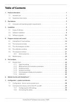
Table of Contents 1. Product information . . . . . . . . . . . . . . . . . . . . . . . . . . . . . . . . . . . . . . . . . . . . . . . . . . . . . . . . . . . . . . . . . . . 1 1.1 Computer and operating system require ents. . . . . . . . . . . . . . . . . . . . . . . . . . . . . . . . . . . . . 7 m 4. Program structure and control . . . . . . . . . . . . . . . . . . . . . . . . . . . . . . . . . . . . . . . . . . . . . . . . . . . . . . . . . 16 4.1 ClarityChrom® main window. . . . . . . . . . . . . . . . . . . . . . . . . . . . . . . . . . . . . . . . . . . . . . . . . . . . 16 Program start...
Open the catalog to page 3
Configuring the router . . . . . . . . . . . . . . . . . . . . . . . . . . . . . . . . . . . . . . . . . . . . . . . . 30 Integrating the LAN into a company network. . . . . . . . . . . . . . . . . . . . . . . . . . . . . 30 Troubleshooting LAN . . . . . . . . . . . . . . . . . . . . . . . . . . . . . . . . . . . . . . . . . . . . . . . . . 31 Configuration by downloading from the device . . . . . . . . . . . . . . . . . . . . . . . . . . . . . . . . . . . 31 Configuration – KNAUER pumps . . . . . . . . . . . . . . . . . . . . . . . . . . . . . . . . . . . . . . . . . . . . . . . . 32 Configuration...
Open the catalog to page 4
8. Setup – systems and instruments . . . . . . . . . . . . . . . . . . . . . . . . . . . . . . . . . . . . . . . . . . . . . . . . . . . . . . . 91 Duration of of a time program. . . . . . . . . . . . . . . . . . . . . . . . . . . . . . . . . . . . . . . 93 Event table . . . . . . . . . . . . . . . . . . . . . . . . . . . . . . . . . . . . . . . . . . . . . . . . . . . . . . . 93 8.1 Autosampler. . . . . . . . . . . . . . . . . . . . . . . . . . . . . . . . . . . . . . . . . . . . . . . . . . . . . . . . . . . . . . . . . . 94 8.1.1 Mode, time and temperature . . . . . . . . . . . . . . . . ....
Open the catalog to page 5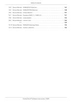
Table of contents 10.4 Device Monitor – KNAUER UV Detectors. . . . . . . . . . . . . . . . . . . . . . . . . . . . . . . . . . . . . . . . . 147 10.5 Device Monitor – KNAUER PDA Detectors . . . . . . . . . . . . . . . . . . . . . . . . . . . . . . . . . . . . . . . 148 10.6 Device Monitor – Virtual detector. . . . . . . . . . . . . . . . . . . . . . . . . . . . . . . . . . . . . . . . . . . . . . . 151 10.7 Device Monitor – Assistant ASM 2.1L / ASM 2.2L. . . . . . . . . . . . . . . . . . . . . . . . . . . . . . . . . . 151 10.8 Device Monitor – autosamplers. . . . . . . . . . . . . . . . . ....
Open the catalog to page 6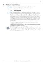
1. Product information Note: Lost or stolen hardware keys (dongles) will not be replaced. If the don le is lost, the license for using the software is lost. g 1.1 Intended use Note: Only use the device for applications that fall within the range of the inten ded use. Otherwise, the protective and safety equipment of the device could fail. The chromatographic station ClarityChrom® is an effective tool for the acqui sition, processing and evaluation of data from any as well as for the con rolling of t KNAUER HPLC systems. Additionally, further devices and systems with a digital interface are...
Open the catalog to page 7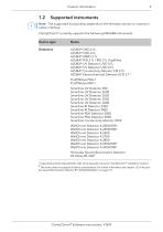
1.2 Supported instruments Note: The supported functionality depends on the firmware version or communi cation interface. ClarityChrom® currently supports the following KNAUER instruments: Device type AZURA® DAD 6.1L AZURA® DAD 2.1L AZURA® MWD 2.1L AZURA® RID 2.1L / RID 2.1L HighFlow AZURA® UV Detector UVD 2.1L AZURA® UV Detector UVD 2.1S AZURA® Conductivity Monitor CM 2.1S AZURA® Electrochemical Detector ECD 2.11 PLATINblue PDA-1 PLATINblue MW-1 Smartline UV Detector 200 Smartline UV Detector 2500 Smartline UV Detector 2520 Smartline UV Detector 2550 Smartline UV Detector 2600 Smartline RI Detector...
Open the catalog to page 8
Device type AZURA® Pump P 8.1L (isocratic, HPG, p-max mode) AZURA® Pump P 6.1L (isocratic, LPG, HPG, p-max mode, no constant pressure mode) AZURA® Pump P 2.1L (isocratic, LPG, HPG, no isobar mode) AZURA® Pump P 2.1S/P 4.1S (isocratic, HPG) PLATINblue Pump P-1 (isocratic, LPG, HPG) Smartline Pump 1050 (isocratic, LPG, HPG) Smartline Pump 1000 (isocratic, LPG, HPG) Smartline Pump 100 (isocratic, HPG) Smartline Pump 1800 (isocratic, LPG, HPG) WellChrom Pump K-1800 (isocratic, LPG, HPG) WellChrom Pump K-120 (isocratic, HPG) WellChrom Pump K-501 (isocratic, HPG) WellChrom Pump K-1000 (isocratic, LPG,...
Open the catalog to page 9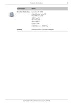
Device type Fraction Collectors Smartline FC 3050 KNAUER Multi Valve FC KNAUER Virtual FC ISCO Foxy R1 ISCO Foxy R2 ISCO Foxy Jr. Buechi C660 LABOCOL Vario 4000/Plus Bronkhorst Mini-Coriflow Flowmeter ClarityChrom® Software instructions, V1670
Open the catalog to page 10
2. Key features Measuring Simultaneous data acquisition from up to four independent chromatographs. One chromatograph can acquire data from up to 12 detectors. Only two fullequipped systems per computer are recommended. Integration There is extensive possibility to modify chromatograms. The chromatogram can be changed by entering global parameters or interactively, through direct graphic modification of the baseline. Overlay Simultaneously displays a virtually unlimited number of chromatograms and their mathematical modification; for example, mutual deductions or derivations of any order. Calibration...
Open the catalog to page 11
Key features6 Method and calibration history Each chromatogram can easily be displayed under the same conditions as when it was printed, exported or saved. Column performance Calculation of peaks in terms of symmetry, efficiency, resolution; all by several methods (tangent, moments, etc.). Batch Automatically batch processes, displays, exports or prints any number of chromatograms. User calculations Users can define custom calculations in the result and summary tables. Using the integrated editor you can create your own columns from original columns and individual mathematical functions. User...
Open the catalog to page 12All KNAUER catalogs and technical brochures
 Pump P 2.1S/P 4.1S Instructions
60 Pages


- Analysis software
- Control software
- Windows software
- Automated software
- Acquisition software
- Data management software
- Digital thermoregulator
- Chromatography system
- Laboratory bottle
- Cooling thermostat
- Laboratory pump
- Laboratory thermostat
- Gas pump
- Validation software
- Data processing software
- Liquid chromatography system
- Chromatography column
- Chromatography detector