- Catalogs
- LDR Medical
- Anterior Cervical Plate
Anterior Cervical Plate

Anterior Cervical Plate
- Step 1 - Disc Location and Vertebral Space Preparation: Identify the affected level using fluoroscopy, place the retractor, distract the intersomatic space, and proceed with disc resection.
- Step 2 - Plate Selection and Bending: Determine the appropriate plate length and adjust using the plate bender if necessary.
- Step 3 - Plate Positioning: Stabilize the plate on the vertebrae using temporary fixation pins.
- Step 4 - Screw Path Preparation and Creation: Choose the appropriate drill guide and drill bit based on the screw type and create the screw path.
- Step 5 - Screw Insertion: Insert screws using a self-retaining screwdriver, ensuring the central screw is variable and perpendicular to the plate.
- Step 6 - Final Locking: Perform final locking by tightening screws until they slide under the clip, confirmed by tactile, auditory, and visual checks.
Catalog excerpts

France Hôtel de Bureaux 1, 4 rue Gustave Eiffel, 10430 Rosières Près Troyes Adresse postale : Technopôle de l’Aube BP 2 10902 Troyes Cedex 9, France +33 (0)3 25 82 32 63 China Beijing Global Trade Center #36 North Third Ring Road East, Unit 06, Level 19, Building A, Dongcheng District, Beijing, China, 100013 +86 10 58256655 Brazil Av. Pereira Barreto, 1395 Torre sul - CJ 193 - Bairro Paraiso Santo André - São Paulo CEP : 09190-610 Brazil +55 11 43327755 United States 13785 Research Boulevard Suite 200 Austin, TX 78750 USA 512.344.3333 LDR, LDR Spine, LDR Médical, BF+, BF+(ph), Easyspine, C-Plate, SpineTune, MC+, Mobi, Mobi-C, Mobi-L, Mobidisc, ROI, ROI-A, ROI-T, ROI-C, Avenue L and verteBRIDGE are trademarks or registered trademarks of LDR Holding Corporation or its affiliates in France, the United States or other countries. ANTERIOR CERVICAL PLATE SURGICAL TECHNIQUE Document intended for the exclusive use of healthcare professionals. C-Plate®- Non-sterile anterior cervical plate system- is a class IIb CE marked medical device made by the LDR Medical S.A.S. Company and for which the conformity assessment was carried out by the notified body G-Med N°0459. C-Plate® is an anterior cervical plate system intended to provide immobilization and stabilization of spinal segments during the development of a cervical spinal fusion. Before any surgical procedure, read carefully the instructions and the surgical technique.
Open the catalog to page 1
SURGICAL TECHNIQUE C-Plate Table of contents - Disc location and vertebral space preparation . . . . . . . . . . . . . . . . . . . . . . . . . . . . . . . . . . . . . . . . 3 - Plate selection and bending . . . . . . . . . . . . . . . . . . . . . . . . . . . . . . . . . . . . . . . . . . . . . . . . . . . . . . . . . . . . . . . . . . . . 4 - Screw path preparation and creation . . . . . . . . . . . . . . . . . . . . . . . . . . . . . . . . . . . . . . . . . . . . . . . . . . . . . . 7 4a. Drill guide positioning . . . . . . . . . . . . . . . . . . . . . . . . . . . . . . . . . . . . . . . ....
Open the catalog to page 2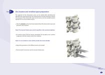
Disc location and vertebral space preparation The approach of the intersomatic space can be realised after identifying the affected level under fluoroscopy. The surgical protocol and the technique used for the exposure of the intersomatic space are the same as for the standard anterior approach for cervical vertebral surgery. Place the retractor on the level to be treated, distract the intersomatic space and proceed to disc resection. Note: The retractor fixation pins must be parallel to the vertebral endplates. Be careful to take off all the anterior osteophytes for the plate to be in perfect...
Open the catalog to page 3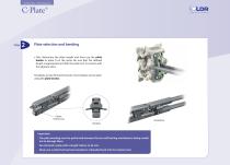
SURGICAL TECHNIQUE Plate selection and bending First, determine the plate length and then use the plate holder to place it on the spine. Be sure that the defined length is appropriate and that the plate isn’t in contact with the adjacent discs. The plates are pre-formed; however, more lordosis can be given using the plate bender. Elastic locking ring Unbending Bending Important: - The plate bending must be performed between the two self-locking mechanisms, being careful not to damage them. - Do not bend a plate with a length inferior to 46 mm. - Never put a plate that has been bended or unbended...
Open the catalog to page 4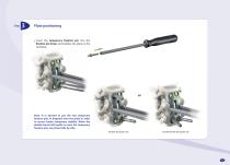
Plate positioning Insert the temporary fixation pin into the fixation pin driver and stabilize the plate on the vertebrae. Note: It is advised to put the two temporary fixation pins in diagonal onto the plate in order to ensure better temporary stability. When the double-barrel drill guide is used, the temporary fixation pins are placed side by side. Simple drill guide use Double-barrel drill guide use
Open the catalog to page 5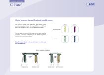
SURGICAL TECHNIQUE Choice between the semi-fixed and variable screws 3,5 mm Two types of screws exist: semi-fixed and variable. These screws are available in two diameters (3.5 mm and 4.0 mm) and in five lengths (10 to 18 mm by increment of 2 mm). Semi-fixed screws The two types of screws can be used on the same assembly according to surgeon preference and the desired angulation between the screws and the plate. Variable screws Note: The screw placed in the central hole of the plate must be a variable screw. Screw insertion angulation Axial plan Sagittal plan Variable screws Semi-fixed screws...
Open the catalog to page 6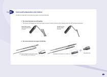
Screw path preparation and creation In order to create the screw path, two steps must be performed: 1 - The choice between two drill guides: This choice will depend on the screw type to insert in order to ensure their sliding under the self-locking mechanism. Semi-fixed screws: Use the double-barrel drill guide Variable screws: Use the simple drill guide 2 - The choice between two types of drill bits: Fixed-stop drill bit for screws with a length of 14 mm Ø3.5 mm or Ø4.0 mm Adjustable stop
Open the catalog to page 7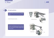
SURGICAL TECHNIQUE Drill guide positioning Important: Make sure that there are no temporary fixation pins in the holes where the drill guide will be placed. Place the drill guide on the plate. Double-barrel drill guide Important: The drill guide spurs must be in contact with the plate. If not, the angulation given to the screw path may be unpredictable, potentially prohibiting final locking from occuring (self locking mechanism sliding over screw heads). Simple drill guide
Open the catalog to page 8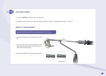
Screw path creation Choose the drill bit according to the screw diameter. Two different types of drill bits are available: fixed stop drill bit – Option A or Adjustable stop drill bit – Option B Option A – Fixed stop drill bit Important: The fixed stop drill bit can only be used with 14 mm screws. Assemble the quick-connect handle and the drill bit. Insert the drill bit into the drill guide that has been positioned beforehand and drill the screw path to the mechanical stop. Remove the drill bit first and then the drill guide. Mechanical stop
Open the catalog to page 9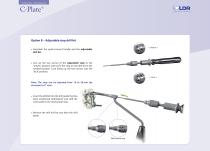
SURGICAL TECHNIQUE Option B – Adjustable stop drill bit « Unlock » Assemble the quick-connect handle and the adjustable drill bit. Line up the two arrows of the adjustable stop to the “unlock” position and screw the stop on the drill bit to the needed position. Lock lining up the two arrows into the “lock” position. « Lock » Note: The stop can be adjusted from 10 to 20 mm (by increment of 1 mm). Insert the drill bit into the drill guide that has been positioned beforehand and drill the screw path to the mechanical stop. Remove the drill bit first and then the drill guide. Mechanical stop
Open the catalog to page 10All LDR Medical catalogs and technical brochures
 C-PLATE
2 Pages
 ROI-A:Patient EDUCATION
16 Pages
 ROI-A
ROI-A3 Pages
 MC+
MC+2 Pages
 ROI - C
2 Pages
 SpineTune ® TL
2 Pages
 ROI
ROI6 Pages
 Easyspine®
41 Pages
 MC+®
MC+®8 Pages
 ROI-C®
18 Pages
 Mobi-C® Plug & Fit
14 Pages

- Bone plate
- Interbody fusion cage
- Bone substitute
- PEEK interbody fusion cage
- Anterior interbody fusion cage
- Lumbar interbody fusion cage
- Arthrodesis plate
- Orthopedic surgery bone substitute
- Spinal stabilization system
- Posterior spinal osteosynthesis unit
- Metallic arthrodesis plate
- Cervical interbody fusion cage
- Adult spinal osteosynthesis unit
- Synthetic bone substitute
- Locking arthrodesis plate
- Posterior interbody fusion cage
- Transforaminal interbody fusion cage
- Rigid bone substitute
- Cervical vertebra arthrodesis plate
- Thoraco-lumbar osteosynthesis unit