- Catalogs
- LDR Medical
- Easyspine®
Easyspine®

Easyspine®
The document details the surgical technique for the EASYSPINE® Thoraco-Lumbar Posterior Osteosynthesis System, a CE marked medical device by LDR Medical S.A.S. It is designed for healthcare professionals to aid in the immobilization and stabilization of spinal segments for treating thoracic and lumbar spine instabilities or deformities.
Specifications
The system comprises standard and alpha screws, rods with varying rigidities, and optional components like transverse connections and hooks. The screws allow for ±20° angulation, with alpha screws offering additional flexibility in the sagittal plane.
Procedures
- Site Preparation and Screw Path Creation: An adjustable square awl is used to perforate the cortex and prepare the screw entry point, with a curved pedicle probe creating the pedicle path.
- Screw Path Verification: The path is verified using a sounder and fluoroscopy to avoid false passages.
- Screw Selection and Insertion: Standard or alpha screws are chosen based on anatomical needs and inserted using a self-retaining screw holder.
- Rod Selection and Insertion: Rod length and rigidity are determined, and rods are inserted into screw heads, allowing for sequential loading if necessary.
- Correction Maneuvers: Compression or distraction maneuvers are performed as needed before final tightening.
- Final Tightening: The rod is properly seated before final tightening, confirmed by an audible double "click".
Options
- Transverse Connection: Enhances construct stability, adjustable via oblong slots.
- Spondylolisthesis Reduction: Combines bony and mechanical reduction techniques using LP screws.
- Trauma and Fracture Reduction: Specific techniques for addressing spinal trauma.
- Thoracic Construct: Techniques for thoracic spine stabilization.
- Pedicle and Laminar Hooks: Additional options for specific anatomical requirements.
- Revision: Guidelines for revising previous constructs.
Conclusion
The EASYSPINE® system offers a comprehensive solution for spinal stabilization, providing flexibility in screw and rod selection to accommodate various surgical needs and patient anatomies.
This document provides a detailed surgical technique for the Easyspine system, a posterior osteosynthesis system used for spinal stabilization and immobilization. It is intended for healthcare professionals and outlines procedures for various spinal surgeries, including trauma and fracture reduction, thoracic constructs, and the use of pedicle and laminar hooks.
LP Screw Insertion and Reduction
The procedure begins with the insertion of LP screws in L5, ensuring the screw path is extra-articular and convergent for optimal force distribution. The reduction is controlled with sagittal fluoroscopy, and final tightening is performed once satisfactory reduction is achieved. The reduction can be stopped at any time to prevent excessive force on nerve roots or screws.
Trauma and Fracture Reduction
Pedicle trajectories are created above and below the fractured vertebrae. The distractor's blades are positioned at the base of the screw heads, and distraction is performed to maintain vertebral body height. Controlled reduction is achieved by pressing reduction levers, with fluoroscopy used to ensure proper reduction and neural protection.
Rod Insertion and Final Tightening
The rod is inserted into the screw heads, with the Easyspine system allowing for sequential loading. Final tightening of set screws is performed after rod insertion on both sides of the construct.
Thoracic Construct
Thoracic screw entry points are created using an adjustable square awl, and pedicle paths are prepared with a curved probe. The procedure follows the Easyspine classical technique for screw insertion and rod placement.
Pedicle and Laminar Hooks
Pedicle hooks are positioned after preparing the lower articular process. The hook is compressed against the pedicle using distraction forceps. Laminar hooks are inserted following preparation of the vertebral lamina, with the rod exceeding the construct for hook implantation.
Revision Procedure
If a set screw cannot be loosened, an ablation tool is used. The T-handle is screwed onto the hook rod, and counter-torque is applied to facilitate unscrewing.
Conclusion
The Easyspine system provides a comprehensive approach to spinal stabilization, with detailed steps for various surgical techniques. Proper adherence to the outlined procedures ensures effective treatment of spinal instabilities or deformities.
Catalog excerpts

France Hôtel de Bureaux 1, 4 rue Gustave Eiffel, 10430 Rosières Près Troyes Adresse postale : Technopôle de l’Aube BP 2 10902 Troyes Cedex 9, France +33 (0)3 25 82 32 63 China Beijing Global Trade Center #36 North Third Ring Road East, Unit 06, Level 19, Building A, Dongcheng District, Beijing, China, 100013 +86 10 58256655 Brazil Av. Pereira Barreto, 1395 Torre sul - CJ 193 - Bairro Paraiso Santo André - São Paulo CEP : 09190-610 Brazil +55 11 43327755 United States 13785 Research Boulevard Suite 200 Austin, TX 78750 USA 512.344.3333 LDR, LDR Spine, LDR Médical, BF+, BF+(ph), Easyspine, C-Plate, SpineTune, MC+, Mobi, Mobi-C, Mobi-L, Mobidisc, ROI, ROI-A, ROI-T, ROI-C, Avenue L and verteBRIDGE are trademarks or registered trademarks of LDR Holding Corporation or its affiliates in France, the United States or other countries. THORACO-LUMBAR POSTERIOR OSTEOSYNTHESIS SYSTEM SURGICAL TECHNIQUE Document intended for the exclusive use of healthcare professionals. EASYSPINE®- Sterile posterior osteosynthesis system- is a class IIb CE marked medical device made by the LDR Medical S.A.S. Company and for which the conformity assessment was carried out by the notified body G-Med N°0459. The EASYPSINE® system is a posterior, pedicle fixation system intended to provide immobilization and stabilization of spinal segments. It is a posterior osteosynthesis system used in the treatment of instabilities or deformities of thoracic and lumbar spine, in association with bone graft. Before any surgical procedure, read carefully the instructions and the surgical technique.
Open the catalog to page 1
SURGICAL TECHNIQUE - Site preparation and screw path creation . . . . . . . . . . . . . . . . . . . . . . . . . . . . . . . . . . . . . . . . . . . . . 3 - Screw path verification . . . . . . . . . . . . . . . . . . . . . . . . . . . . . . . . . . . . . . . . . . . . . . . . . . . . . . . . . . . . . . . . . . . . . . . . . 4 - Screw selection (standard or alpha) and insertion . . . . . . . . . . . . . . . . . . . . . . . . . . . . . . . . 5 - Traumatism and fracture reduction . . . . . . . . . . . . . . . . . . . . . . . . . . . . . . . . . . . . . . . . . . . . . . . . . . . . . 19
Open the catalog to page 2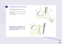
Site preparation and screw path creation Use the adjustable square awl to perforate the cortex Prepare the entry point of the screw using the chamfer on the square awl. This slight opening of the entry point will facilitate further screw insertion. Note: The square awl has an integrated and adjustable depth measurement from 10mm to 50mm. This unique design allows the depth adjustment of the instrument in order to increase surgical procedure precision and safety.
Open the catalog to page 3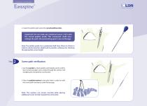
SURGICAL TECHNIQUE Create the pedicle path using the curved pedicle probe. Important: Do not make any rotational moves (>30°) with the curved pedicle probe. This movement could overenlarge the path, thus preventing good screw anchorage. Note: The pedicle probe has a graduated shaft from 30mm to 55mm in order to control insertion depth and to provide a reference for choosing the appropriate screw length. Screw path verification Use the sounder to check pedicle wall integrity and to confirm that no false passages were created through the anterior wall (straight part) and pedicles (curved part)....
Open the catalog to page 4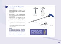
Screw selection (standard or alpha) and insertion Standard and alpha screws can be used on a same construct based on surgeon preferences and patient anatomical needs. 20° 20° Alpha screws offer ± 20° (axial and sagittal plane) to maintain flat on flat contact with the rod regardless of the screw angulation. Standard Screw Vis standard Alpha Screw Vis alpha Standard screws offer ± 20° of angulation in the axial plane, monoaxiale capacity in the sagittal plane may be useful when treating certain indications (spondylolisthesis reduction, scoliosis, trauma...). Select a type (standard or alpha) and...
Open the catalog to page 5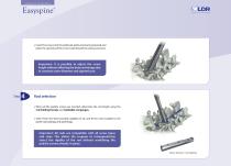
SURGICAL TECHNIQUE Insert the screws into the pedicular paths previously prepared and place the opening of the screw head toward the spinous process. Important: It is possible to adjust the screw height without effecting the bony anchorage due to constant outer diameter and tapered core. Rod selection When all the pedicle screws are inserted, determine the rod length using the rod holding forceps and malleable rod gauges. Select from the three possible rigidities (S, M, and R) the most suitable to the patient physiology and pathology. Important: All rods are compatible with all screw types and...
Open the catalog to page 6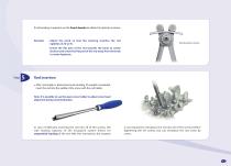
If rod bending is required, use the french bender to obtain the desired curvature. - Adjust the knob so that the marking matches the rod rigidities (S, M or R). Bending step: Lordosis - Orient the flat part of the rod towards the knob to create lordosis and orient the flat part of the rod away from the knob to create kyphosis. Rod insertion After rod length is determined and bending (if needed) completed, insert the rod into the saddle of the screw with the rod holder. Note: It is possible to use the open screw holder to adjust screw head alignment during rod introduction. In case of difficulty...
Open the catalog to page 7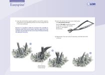
SURGICAL TECHNIQUE 1. Insert the rod into the superior pedicle screw of the construct and perform a pre-tightening of the set screw to keep the rod in the screw opening. 2. Insert the rod into the next screw head using the rod insertion forceps. Pass the T25 shaft through the window in the jaws of the rod insertion forceps to pre-tighten the set screw. Remark: It is possible to slide the rod down the assembly to bring the stop of the rod in contact with the upper screw. The rod does not protrude from the screw head, thereby protecting the adjacent facet joint. 3. Repeat step 2 for each screw,...
Open the catalog to page 8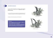
Correction maneuvers If necessary before final tightening, compression and/or distraction maneuvers can be performed with the compression forceps or distraction forceps. Lock one of the screws in the segment to be translated (distraction or compression) and place the chosen forceps against the screw heads. Compress or distract by pressing on the locked screw. Distraction maneuver Important: - The pre-tightening of the screw allows a sliding of the rod without any risk of expulsion. - The flat part of the rod minimizes unwanted rod rotation and provides a visual reference for sagittal plane correction...
Open the catalog to page 9All LDR Medical catalogs and technical brochures
 C-PLATE
2 Pages
 ROI-A:Patient EDUCATION
16 Pages
 ROI-A
ROI-A3 Pages
 MC+
MC+2 Pages
 ROI - C
2 Pages
 SpineTune ® TL
2 Pages
 ROI
ROI6 Pages
 Anterior Cervical Plate
15 Pages
 MC+®
MC+®8 Pages
 ROI-C®
18 Pages
 Mobi-C® Plug & Fit
14 Pages

- Bone plate
- Interbody fusion cage
- Bone substitute
- PEEK interbody fusion cage
- Anterior interbody fusion cage
- Lumbar interbody fusion cage
- Arthrodesis plate
- Orthopedic surgery bone substitute
- Spinal stabilization system
- Posterior spinal osteosynthesis unit
- Metallic arthrodesis plate
- Cervical interbody fusion cage
- Adult spinal osteosynthesis unit
- Synthetic bone substitute
- Locking arthrodesis plate
- Posterior interbody fusion cage
- Transforaminal interbody fusion cage
- Rigid bone substitute
- Cervical vertebra arthrodesis plate
- Thoraco-lumbar osteosynthesis unit