- Catalogs
- LDR Medical
- Mobi-C® Plug & Fit
Mobi-C® Plug & Fit

Mobi-C® Plug & Fit
The document details the surgical technique for the MOBI-C® cervical disc prosthesis, a class IIb CE marked medical device by LDR Medical S.A.S. It is used for cervical intervertebral disc replacement to restore motion and disc height at levels C3/C4 to C6/C7. It is intended for healthcare professionals, emphasizing the importance of thoroughly reading instructions before surgery.
Implant height should not exceed that of healthy adjacent discs, verified by x-ray and intra-operative measurement. The surgical approach is similar to anterior cervical arthrodesis, requiring intraoperative x-rays for accurate positioning.
Proper patient positioning is crucial for correct prosthesis orientation and alignment. The patient should be in a neutral position to avoid hyperextension, maintaining this throughout the surgery.
- Step 1: Partial Discectomy - Perform a classic discectomy, removing anterior osteophytes.
- Step 2: Midline and Width Determination - Use a width gauge to determine vertebral midline and endplate width.
- Step 3: Caspar Distractor Placement - Insert Caspar pins and maintain distraction with a Caspar distractor.
- Step 4: Complete Discectomy - Remove all posterior osteophytes without weakening endplates.
- Step 5: Parallel Distraction - Achieve parallel distraction using distraction forceps and Caspar distractor.
- Step 6: Depth Measurement - Measure vertebral endplate depth using a depth gauge.
- Step 7: Trial Implants - Determine implant size and height using trial implants, ensuring not to exceed healthy disc height.
- Step 8: Loading the Prosthesis - Load the prosthesis onto the implant holder, ensuring correct positioning.
- Step 9: Millimetric Adjustment - Adjust the stop on the implant holder for precise insertion depth.
- Step 10: Prosthesis Insertion - Insert the prosthesis under fluoroscopy, ensuring proper alignment.
- Step 11: Position Checking - Use fluoroscopy to confirm prosthesis position and make adjustments if necessary.
- Step 12: Implant Holder Removal - Remove the implant holder after confirming prosthesis positioning.
- Step 13: Removal of Clamps - Extract clamps using forceps, ensuring proper alignment.
- Step 14: Anchorage Optimization - Optimize prosthesis anchorage by compressing with the Caspar distractor.
- Step 15: Revision - Steps for revising the prosthesis if necessary, including removal of plates.
The document provides a detailed step-by-step guide for the surgical implantation of the MOBI-C® cervical disc prosthesis, emphasizing precision in measurement, positioning, and handling to ensure successful outcomes.
The document provides a detailed surgical technique for the MOBI-C® cervical disc prosthesis, a class IIb CE marked medical device manufactured by LDR Medical S.A.S. It is designed for cervical intervertebral disc replacement at levels C3/C4, C4/C5, C5/C6, and C6/C7 to restore segmental motion and disc height.
The MOBI-C® prosthesis is intended exclusively for healthcare professionals. It is crucial to read the instructions and surgical technique thoroughly before any procedure. The device is sterile and should not be reused once removed.
The document outlines the steps for implant removal, emphasizing the importance of not reusing the prosthesis. The anterior edge of the superior plate of the implant should be grabbed using a needle holder for extraction.
The document lists contact details for LDR Medical S.A.S. offices in France, China, Brazil, and the United States, providing addresses and phone numbers for each location.
LDR, LDR Spine, and other related trademarks are registered trademarks of LDR Holding Corporation or its affiliates in various countries.
Catalog excerpts

France Hôtel de Bureaux 1, 4 rue Gustave Eiffel, 10430 Rosières Près Troyes Adresse postale : Technopôle de l’Aube BP 2 10902 Troyes Cedex 9, France +33 (0)3 25 82 32 63 China Beijing Global Trade Center #36 North Third Ring Road East, Unit 06, Level 19, Building A, Dongcheng District, Beijing, China, 100013 +86 10 58256655 Brazil Av. Pereira Barreto, 1395 Torre sul - CJ 193 - Bairro Paraiso Santo André - São Paulo CEP : 09190-610 Brazil +55 11 43327755 United States 13785 Research Boulevard Suite 200 Austin, TX 78750 USA 512.344.3333 LDR, LDR Spine, LDR Médical, BF+, BF+(ph), Easyspine, C-Plate, SpineTune, MC+, Mobi, Mobi-C, Mobi-L, Mobidisc, ROI, ROI-A, ROI-T, ROI-C, Avenue L and verteBRIDGE are trademarks or registered trademarks of LDR Holding Corporation or its affiliates in France, the United States or other countries. CERVICAL DISC PROSTHESIS SURGICAL TECHNIQUE Document intended for the exclusive use of healthcare professionals. MOBI-C®- Sterile cervical disc prosthesis- is a class IIb CE marked medical device made by the LDR Medical S.A.S. Company and for which the conformity assessment was carried out by the notified body G-Med N°0459. MOBI-C® prosthesis is a device for cervical intervertebral disc replacement (C3/C4, C4/C5, C5/C6, C6/C7) in order to restore segmental motion and disc height. Before any surgical procedure, read carefully the instructions and the surgical technique.
Open the catalog to page 1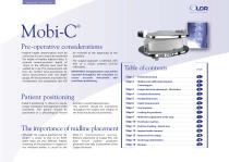
SURGICAL TECHNIQUE Pre-operative considerations Implant height determination must be carried out in such a way as to not exceed the height of healthy adjacent discs. A minimal antero-posterior depth of 14mm at the affected level must be verified by x-ray. This measurement will then be verified intra-operatively by direct measurement with the depth gauge. All measurements must take into consideration any osteophytes that will be resected at the beginning of the procedure. The surgical approach is identical with that of a classic anterior cervical arthrodesis. IMPORTANT: Intraoperative x-rays will...
Open the catalog to page 2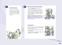
Partial discectomy Proceed with a classic discectomy. Start with the anterior portion of the disc (annular tissue) releasing as much of the uncus as possible. Take care to remove all anterior osteophytes. Midline and width determination Insert the width gauge into the disc space. Position the width gauge flat on the inferior endplate, in contact with the base of the uncus. Once the proper width is selected and the width gauge is centered on the vertebra a reference mark can be made on the superior vertebra to identify the midline. Note: The center reference point, located on the width gauge,...
Open the catalog to page 3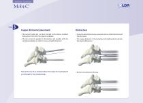
SURGICAL TECHNIQUE Caspar distractor placement The second Caspar pin is in turn inserted in the inferior vertebral body about 5mm from the superior endplate. Using the distraction forceps, proceed with an initial distraction of the disc space. The pins must be parallel to themselves and parallel with the vertebral endplates in order to ensure parallel distraction. The Caspar distractor is then attached and tightened to maintain the desired distraction. Note: In the case of a 2-level procedure, the Caspar pin may be placed at mid-height in the vertebral body. Remove the distraction forceps.
Open the catalog to page 4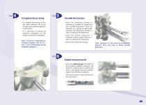
Complete discectomy Parallel distraction Insert the distraction forceps as posterior as possible. A progressive and parallel distraction must be obtained. It is advised to alternately lateralize the distraction forceps in order to optimize the distraction. A complete discectomy of the disc space between the uncus and up to the posterior ligament is performed. It is important to remove all posterior osteophytes on the superior and inferior endplates. Once the desired distraction is obtained, lock the Caspar distractor in order to maintain the distraction. Note: To prevent weakening the vertebral...
Open the catalog to page 5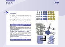
SURGICAL TECHNIQUE Trial implants The depth and width measurements previously taken help determine the trial sizes to use. The trials will determine the final implant height to be used as well as implant size (width and depth). Each size is color coded. Available heights are 4.5, 5, 6, and 7mm*. Trialing should begin with a height that does not exceed the height of healthy adjacent discs. The trial is screwed onto the trial implant holder and, under fluoroscopy, inserted into the disc space. Important: It is imperative to cover a maximum of the vertebral endplates without exceeding their depth....
Open the catalog to page 6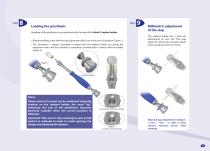
Loading the prosthesis Handling of the prosthesis is accomplished with the help of the Mobi-C implant holder. Before handling, check that the stop adjustment dial is set to the zero (0) position (Figure 1). The "prosthesis + clamps" assembly is loaded onto the implant holder by turning the impaction knob until the assembly is completely screwed and in contact with the holder (Figure 2). Millimetric adjustment of the stop The implant holder has a stop (set beforehand on zero (0)). This stop allows for setting the insertion depth of the prosthesis from 0 to 5mm. Impaction Knob Notes: Visual control...
Open the catalog to page 7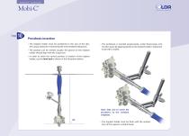
SURGICAL TECHNIQUE Prosthesis insertion The implant holder must be positioned in the axis of the disc, the Caspar distractor maintaining the intervertebral distraction. The position can be verified visually: the groove on the implant holder should align with the Caspar pin. The prosthesis is inserted progressively, under fluoroscopy, into the disc space by tapping gently on the implant holder's impaction knob with a mallet. In order to check the correct position in rotation of the implant holder, use the level rod as shown in the illustration below. Note: Take care to center the prosthesis on...
Open the catalog to page 8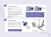
Position checking – lateral view Millimetric readjustment of prosthesis position under fluoroscopy. Fluoroscopic control facilitates assessment of correct prosthesis position. Release the Caspar in order to put the vertebral endplates in parallel. The antero-posterior position of the prosthesis in the intervertebral space can be adjusted, if necessary, with millimetric adjustment of the implant holder's stop. Note: From the lateral view, visual assessment of the alignment of the tabs on the inferior plate is used to control the position of the prosthesis in rotation. Reminder: The prosthesis...
Open the catalog to page 9All LDR Medical catalogs and technical brochures
 C-PLATE
2 Pages
 ROI-A:Patient EDUCATION
16 Pages
 ROI-A
ROI-A3 Pages
 MC+
MC+2 Pages
 ROI - C
2 Pages
 SpineTune ® TL
2 Pages
 ROI
ROI6 Pages
 Easyspine®
41 Pages
 Anterior Cervical Plate
15 Pages
 MC+®
MC+®8 Pages
 ROI-C®
18 Pages

- Bone plate
- Interbody fusion cage
- Bone substitute
- PEEK interbody fusion cage
- Anterior interbody fusion cage
- Lumbar interbody fusion cage
- Arthrodesis plate
- Orthopedic surgery bone substitute
- Spinal stabilization system
- Posterior spinal osteosynthesis unit
- Metallic arthrodesis plate
- Cervical interbody fusion cage
- Adult spinal osteosynthesis unit
- Synthetic bone substitute
- Locking arthrodesis plate
- Posterior interbody fusion cage
- Transforaminal interbody fusion cage
- Rigid bone substitute
- Cervical vertebra arthrodesis plate
- Thoraco-lumbar osteosynthesis unit