- Catalogs
- LDR Medical
- ROI-C®
ROI-C®

ROI-C®
The document details the surgical technique for the ROI-C® sterile anterior cervical cage, a class IIb CE marked medical device designed for cervical vertebrae fixation from levels C3 to C7. Manufactured by LDR Medical S.A.S., it is intended for healthcare professionals.
Step-by-Step Surgical Procedure
- Step 1 - Disc Location: Identify the affected level using fluoroscopy, following the standard anterior cervical approach.
- Step 2 - Discectomy: Place Caspar pins 8mm from the endplates and distract the intersomatic space for disc removal.
- Step 3 - Freshening the Vertebral Endplates: Prepare the implant space and grafting surfaces with a curette and rasp to promote fusion.
- Step 4 - Trial Implant Selection: Choose trial implants based on depth, width, and height, identified by color code.
- Step 5 - Cage Selection: Select the final implant based on the trial implant's color code and height.
- Step 6 - Cage Preparation: Fill the fusion chamber with autograft or bone substitute and prepare the cage for insertion.
- Step 7 - Loading the Cage on the Implant Holder: Secure the cage on the implant holder using a threaded axis and impaction knob.
- Step 8 - Cage Positioning: Insert the cage into the intervertebral space under fluoroscopy, adjusting for optimal positioning.
- Step 9 - Anchoring Plates Positioning: Insert and impact half anchoring plates to secure the cage.
- Step 10 - Implant Holder Removal and Final Control: Remove the implant holder and verify final positioning under fluoroscopy.
- Step 11 - Revision: Outline procedures for plate and cage removal, including specific instruments.
Conclusion
The document provides comprehensive instructions for the surgical implantation of the ROI-C® cervical cage, highlighting the importance of precise positioning and secure anchoring for successful outcomes.
Catalog excerpts

TECHOP_ROICCOUV_EN _New:Mise en page 1 France Hôtel de Bureaux 1, 4 rue Gustave Eiffel, 10430 Rosières Près Troyes Adresse postale : Technopôle de l’Aube BP 2 10902 Troyes Cedex 9, France +33 (0)3 25 82 32 63 China Beijing Global Trade Center #36 North Third Ring Road East, Unit 06, Level 19, Building A, Dongcheng District, Beijing, China, 100013 +86 10 58256655 Brazil Av. Pereira Barreto, 1395 Torre sul - CJ 193 - Bairro Paraiso Santo André - São Paulo CEP : 09190-610 Brazil +55 11 43327755 United States 13785 Research Boulevard Suite 200 Austin, TX 78750 USA 512.344.3333 LDR, LDR Spine, LDR Médical, BF+, BF+(ph), Easyspine, C-Plate, SpineTune, MC+, Mobi, Mobi-C, Mobi-L, Mobidisc, ROI, ROI-A, ROI-T, ROI-C, Avenue L and verteBRIDGE are trademarks or registered trademarks of LDR Holding Corporation or its affiliates in France, the United States or other countries. ANTERIOR CERVICAL CAGE SURGICAL TECHNIQUE Document intended for the exclusive use of healthcare professionals. ROI-C®- Sterile anterior cervical cage- is a class IIb CE marked medical device made by the LDR Medical S.A.S. Company and for which the conformity assessment was carried out by the notified body G-Med N°0459. ROI-C® is intended for fixation of the cervical vertebrae by anterior approach for the levels C3 to C7. Before any surgical procedure, read carefully the instructions and the surgical technique.
Open the catalog to page 1
TECHOP_ROICCOUV_EN _New:Mise en page 1 SURGICAL TECHNIQUE - Freshening the vertebral endplates. . . . . . . . . . . . . . . . . . . . . . . . . . . . . . . . . . . . . . . . . . . . . . . . . . . . . . . . . 4 - Trial implant selection . . . . . . . . . . . . . . . . . . . . . . . . . . . . . . . . . . . . . . . . . . . . . . . . . . . . . . . . . . . . . . . . . . . . . . . . . . . . . 4 - Loading the cage on the implant holder . . . . . . . . . . . . . . . . . . . . . . . . . . . . . . . . . . . . . . . . . . . . . . . . . 8 - Anchoring plates positioning. . . . . . . . . . . . . . . . . ....
Open the catalog to page 2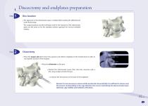
TECHOP_ROI-C_INT_EN _New:Mise en page 1 Discectomy and endplates preparation Step Disc location The approach to the intersomatic space is realised after locating the affected level under fluoroscopy. The surgical protocol and the technique used for the exposure of the intersomatic space are the same as for the standard anterior approach for cervical vertebral surgery.. Discectomy Place the Caspar pins 8mm from the superior and inferior endplates of the treated level in order to not impede insertion of the implant. Place the distractor on the pins. Distract the intersomatic space, then start disc...
Open the catalog to page 3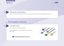
TECHOP_ROI-C_INT_EN _New:Mise en page 1 SURGICAL TECHNIQUE Freshening the vertebral endplates Prepare the implant space and the grafting surfaces with a curette and a rasp. Thorough freshening of the endplates favours the fusion. Trial implant selection Step Trial implant selection The trial implants vary in: depth x width and height. They are identifiable due to a colour code: each colour representing a size (depth x width)
Open the catalog to page 4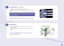
TECHOP_ROI-C_INT_EN _New:Mise en page 1 Depth selection (12 or 14 mm) Insert the chosen trial implant into the intervertebral space. Check under fluoroscopy correct positioning of the trial implant in depth and rotation. Important: The posterior side of the trial implant has to be at a minimum of 1mm from the posterior edge of the vertebra. If not the case, choose a trial implant of inferior depth. Remark: The trial implant hole must be visible, assuring the lack of rotation. Width selection After depth measurement, insert the chosen trial implant into the intervertebral space. Choose the trial...
Open the catalog to page 5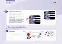
TECHOP_ROI-C_INT_EN _New:Mise en page 1 SURGICAL TECHNIQUE Height selection (from 4,5mm) Insert the trial implant of the colour corresponding to the previously chosen size (depth x width) into the intervertebral space. Release briefly the distraction in order to make sure the trial implant is stable in the intervertebral space. Check under fluoroscopy the consistency between the height of the selected trial implant and the discal height of the adjacent levels. Restore the distraction in order to remove the trial implant from the intervertebral space. Trial implant selection Step Cage selection...
Open the catalog to page 6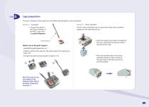
TECHOP_ROI-C_INT_EN _New:Mise en page 1 Cage preparation The fusion chamber of the cages has to be filled with autograft or bone substitute. Option B – Bone substitute The BF+ bone substitute has an anatomical shape and is perfectly adapted to the cage dimensions. Compact the graft in the fusion chamber of the ROI-C cage with the graft compactor. Insert the superior part (dome-shaped) of the bone substitute through the inferior opening of the cage. Graft compactor Option: Use of the graft support: - Assemble the graft support (see 1.a). - Position and lock the cage into the graft support by rotating...
Open the catalog to page 7
TECHOP_ROI-C_INT_EN _New:Mise en page 1 SURGICAL TECHNIQUE Loading the cage on the implant holder Bring the cage close to the implant holder in such a way as to slot the implant holder hook in the notch on the left side of the cage. Secure the cage on the implant holder with the threaded axis by screwing the impaction knob. Threaded axis Impaction knob
Open the catalog to page 8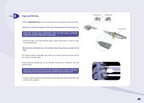
TECHOP_ROI-C_INT_EN _New:Mise en page 1 Cage positioning Standard stop Set the adjustable stop to zero by screwing or unscrewing the impaction knob. Remark: It is up to the surgeon to select the standard stop or the enlarged one. Knurled wheel Important: During cage positioning, make sure the cage is perfectly inserted in the axis of the intersomatic space. OK Insert the cage in the intervertebral space under fluoroscopy in order to verify correct positioning. Remark: From the lateral view, the marker shows the posterior position of the cage. The implant holder’s adjustable stop comes into contact...
Open the catalog to page 9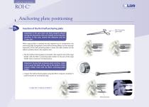
TECHOP_ROI-C_INT_EN _New:Mise en page 1 SURGICAL TECHNIQUE Anchoring plate positioning Step Insertion of the first half anchoring plate ROI-C Anchoring plate holder Important: If the pins have not been properly placed during the discectomy, they can impede anchoring plate insertion. In this case, remove the distractor and the Caspar pins. When cage position is optimal and the segment put in compression, the anchoring plate (composed of two half anchoring plates) can be inserted. Impaction of the half anchoring plates is done one after another (in the inferior vertebra, then in the superior one)....
Open the catalog to page 10All LDR Medical catalogs and technical brochures
 C-PLATE
2 Pages
 ROI-A:Patient EDUCATION
16 Pages
 ROI-A
ROI-A3 Pages
 MC+
MC+2 Pages
 ROI - C
2 Pages
 SpineTune ® TL
2 Pages
 ROI
ROI6 Pages
 Easyspine®
41 Pages
 Anterior Cervical Plate
15 Pages
 MC+®
MC+®8 Pages
 Mobi-C® Plug & Fit
14 Pages

- Bone plate
- Interbody fusion cage
- PEEK interbody fusion cage
- Anterior interbody fusion cage
- Lumbar interbody fusion cage
- Arthrodesis plate
- Orthopedic surgery bone substitute
- Spinal stabilization system
- Posterior spinal osteosynthesis unit
- Metallic arthrodesis plate
- Cervical interbody fusion cage
- Adult spinal osteosynthesis unit
- Synthetic bone substitute
- Locking arthrodesis plate
- Posterior interbody fusion cage
- Transforaminal interbody fusion cage
- Rigid bone substitute
- Cervical vertebra arthrodesis plate
- Thoraco-lumbar osteosynthesis unit