- Catalogs
- Lepu Medical
- LEPU Quant-fluo 800
- Company
- Products
- Catalogs
- News & Trends
- Exhibitions
LEPU Quant-fluo 800
1 /21Pages

LEPU Quant-fluo 800
1 /21Pages
Catalog excerpts

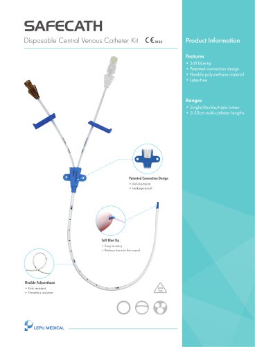
Fluorescence Immunochromatographic Analyzer Fluorescence Immunochromatography Analyzer LEPU Quant-Fluo800
Open the catalog to page 1
Fluorescence Immunochromatographic Analyzer
Open the catalog to page 2
Fluorescence Immunochromatographic Analyzer
Open the catalog to page 3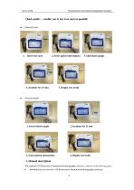
Fluorescence Immunochromatographic Analyzer Quick guide — enable you to use it as soon as possible Internal mode 1. Insert test card 2. Enter patient information 5. Display test result External mode 3. Enter patient information 4. Display test result 1. Manual description The manual of Fluorescence immunochromatography analyzer consists of the flowing parts: Introduction: an overview of Fluorescence immunochromatography analyz
Open the catalog to page 4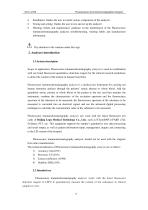
Fluorescence Immunochromatographic Analyzer Installation: Guides the user to install various components of the analyzer; Testing and setting: Guides the user to test and set up the analyzer; Warning, failure and maintenance: guidance on the maintenance of the Fluorescence immunochromatography analyzer, troubleshooting, warning labels and manufacturer information. Pay attention to the cautions under this sign. 2. Analyzer introduction 2.1 System description Scope of application: Fluorescence immunochromatography analyzer is used in combination with our listed fluorescent quantitative detection...
Open the catalog to page 5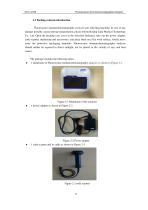
Fluorescence Immunochromatographic Analyzer 2.3 Packing contents introduction Fluorescence immunochromatography analyzer uses individual packing. In case of any damage possibly caused during transportation, please inform Beijing Lepu Medical Technology Co., Ltd. Open the packing case cover in the direction indicated, take out the power adapter, code scanner, mainframe and accessories, and place them on a flat work surface, finally move away the protective packaging materials. Fluorescence immunochromatography analyzer should neither be exposed to direct sunlight, nor be placed in the vicinity...
Open the catalog to page 6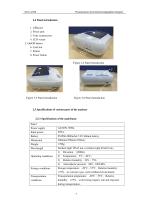
Fluorescence Immunochromatographic Analyzer 2.4 Panel introduction 1. USB port 2. Power port 3. Code scanner port 4. LCD screen 5. On/Off button 6. Card slot 7. Printer 8. Power button Figure 2-4 Panel introduction Figure 2-5 Panel introduction Figure 2-6 Panel introduction 2.5 Specifications of various parts of the analyzer 2.5.1 Specifications of the mainframe Panel Power supply Input power Battery Dimension Incident light 365± nm, excitation light 610± nm。 5 10 1) 2) Operating conditions Storage conditions Storage temperature:-20℃~55℃,Relative humidity: ≤75%,no corrosive gas, well ventilated...
Open the catalog to page 7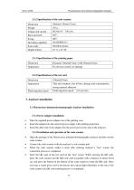
Fluorescence Immunochromatographic Analyzer 2.5.2 Specifications of the code scanner Dimension Decoding capability Scan mode 2.5.3 Specifications of the printing paper Dimension No obvious scratch, no damage 2.5.4 Specifications of the test card Dimension Tidy and complete, free of burr, damage and contamination, strong material adhesion Fluid migration speed:≥10 mm/min。 Fluid migration speed 3. Analyzer installation 3.1 Fluorescence immunochromatography Analyzer installation 3.1.1 Power adapter installation Take the supplied power adapter out of the packing case, Insert the adapter into...
Open the catalog to page 8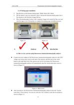
Fluorescence Immunochromatographic Analyzer 3.1.3 Printing paper installation Specifications of the thermal printing paper: Width: 56mm; OD: 40mm; Pull the printer’s top cover upward to open it and put the thermal printing paper into it. Pay attention to the direction of paper delivery. Place the printing paper in place with a segment of paper left outside the flip cover and close the upper cover of the printer to complete the printing paper installation process. 4.1 How to carry out tests using Fluorescence immunochromatography analyzer Connect the power adapter of the Fluorescence immunochromatography...
Open the catalog to page 9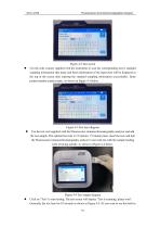
Fluorescence Immunochromatographic Analyzer Figure 4-2 Test screen Use the code scanner supplied with the instrument to scan the corresponding item’s standard sampling information (the name and batch information of the input item will be displayed at the top of the screen after entering the standard sampling information successfully). Enter patient number, patient name. As shown in Figure 4-3 below. Figure 4-3 Test item diagram Use the test card supplied with the Fluorescence immunochromatography analyzer and add the test sample. The optimal test time is 15 minutes. 15 minutes later, insert...
Open the catalog to page 10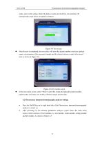
Fluorescence Immunochromatographic Analyzer mode, select in the setting. Select the built-in mode and click Test, the machine will automatically count down, see details as follow). Figure 4-5 Test screen After the test is completed, the test results will show the patient number, test items, patient name, concentration of the measured sample and the clinical reference value of the tested item as shown in Figure 4-6. Figure 4-6 Test results screen In the test results screen, select “Print” to print the results including the patient number, patient name, test items, test results, reference ranges...
Open the catalog to page 11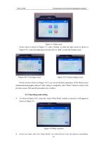
Fluorescence Immunochromatographic Analyzer . Figure 4-7 Main menu In the screen as shown in Figure 4-7, select “Setting” to enter the login screen as shown in Figure 4-8-1, enter the login password and click on “lpkj” to enter the setting screen. Figure 4-8-1 User login screen Figure 4-8-2 System setting screen On the screen as shown in Figure 4-8-2, you can set the basic parameters of the Fluorescence immunochromatography analyzer. After setting is completed, select “Back” button to return to the previous screen. The specific procedures are as follow. 4.2.1 Operating mode setting As shown...
Open the catalog to page 12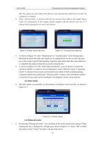
Fluorescence Immunochromatographic Analyzer after the sample has been added. The detector will automatically perform the test after the countdown is complete. When “external Mode” is selected, after the test card has been added to the sample, please follow the requirements of the reagent manual supplied with the detector and wait 5-15 minutes before placing the test card in the detector. Figure 4-10 Inner model detection Figure 4-11 External mode detection As shown in Figure 4-9, select “Manual print” or “Automatic print” in the Printing mode. Manual print means that after each sample test...
Open the catalog to page 13All Lepu Medical catalogs and technical brochures
 Cholesterol meter LP-M3-11
2 Pages
 Nexor 32
2 Pages
 Fluo-1800
28 Pages
 Lepgen-96
1 Page
 Occluder Device
20 Pages
 MemoPart Delivery System Ⅱ
2 Pages
 Neurovascular Products Catalogue
15 Pages
 Anesthesia Products Catalogue
28 Pages
 APTERIAL BLOOD SAMPLING KITS
2 Pages
 Buckle tourniquet Rayband™
2 Pages
 PTCA catheter Hoper™
2 Pages
 PTCA catheter Tadpole™
2 Pages
 PTCA catheter Vesselin®
2 Pages
 PTCA catheter NC Tadpole™
2 Pages
 PCI-Product Catalogue
55 Pages
 Coronary stent Partner
2 Pages
 ELISA 200
75 Pages
 Nexor 96
2 Pages
 COVID-19 Related Products
23 Pages
 Coronary stent GuReater
2 Pages
 Guiding catheter Orien™
2 Pages
 Coronary stent Nano+™
2 Pages
 Coronary stent H-Stent™
2 Pages
 Lepu Medical Product Catalogue
30 Pages
 MemoPart Occluders
1 Page
 Prosthetic Heart Valve
2 Pages
 Blood sampling kit
2 Pages
 Fingertip Pulse Oximeter
2 Pages


- LEPU MEDICAL bone plate
- LEPU MEDICAL compression plate
- LEPU MEDICAL metallic compression plate
- LEPU MEDICAL catheter
- LEPU MEDICAL locking compression plate
- Syringe
- Cannula
- Valve
- LEPU MEDICAL titanium compression plate
- Sterile needle
- Endoscope
- Infusion set
- Distal compression plate
- LEPU MEDICAL balloon catheter
- Medical valve
- Compression bone screw
- Digital radiography system
- LEPU MEDICAL surgical stapler
- Stent
- Metallic compression bone screw