- Catalogs
- MAC Valves Europe Inc
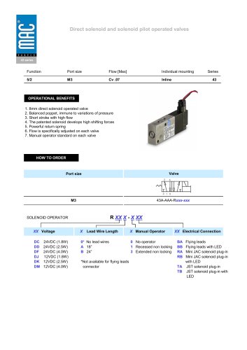
- PROPORTIONAL PRESSURE CONTROLLER
PROPORTIONAL PRESSURE CONTROLLER
1 /89Pages
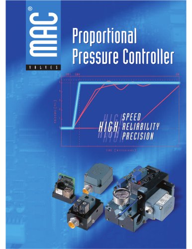
PROPORTIONAL PRESSURE CONTROLLER
1 /89Pages
Catalog excerpts
Section 1 Proportional Pressure Controller 9 Section 2 Proportional Quick Exhaust 65 Section 3 Pressure Control Systems 77 Consult 'Precautions' page 94 before use, installation or service of MAC Valves.
Open the catalog to page 2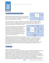
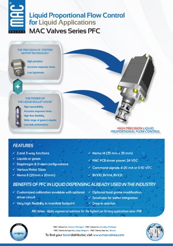
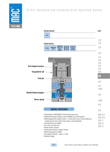
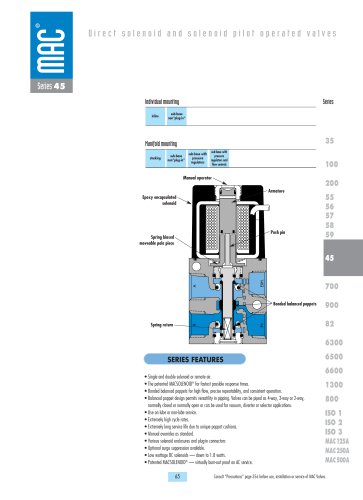
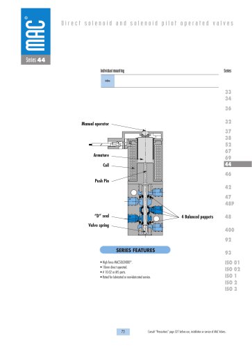
Proportional pressure controller Introduction I. Introducing : Proportional Pressure Controller I or E Input signal The MAC Proportional Pressure Controller, (PPC) is an innovative product which converts an electrical signal into a proportional pneumatic output. The PPC is unlike conventional I/P or V/P transducers. It offers much more in terms of performance, features, and reliability. Inlet pressure The key to the MAC PPCs are two MAC 34, 45, 400, 47, 92 or 93 Series valves that are used to control the output pressure. The valves are operated by the PPCs closed loop electronic control circuit....
Open the catalog to page 3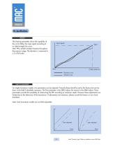
Introduction III. Specifications LINEARITY The linearity parameter shows the capability of the unit to follow the input signal according to an ideal straight line curve. MAC PPCs exhibit excellent linearity throughout the pressure range. The deviation is measured in ± % of full scale. Input signal Output pressure Desired curve Actual curve For single transducer models, two parameters can be adjusted. Primarily these should be set by the factory but can be done in the field if absolutely necessary. The first parameter is the ZERO adjust, the second is the SPAN adjust. These parameters provide...
Open the catalog to page 4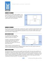
Proportional pressure controller Introduction HYSTERESIS The hysteresis error, sometimes called “deadband”, is the amount of output pressure variance required to cause the PPC to react, making a correction to the output pressure. It is given in percent of full scale pressure, all MAC PPC products perform with minimal hysteresis. MAC Valves states accuracy of the MAC PPCs as overall accuracy. Accuracy is expressed in percent of full scale, which includes hysteresis and linearity. Some suppliers give separate parameters in order to give a better impression. In this case hysteresis and linearity...
Open the catalog to page 5
Introduction IV. Command Signal Options The PPC can be controlled with either an analog command signal or a digital command signal. ANALOG COMMAND SIGNAL The analog command signal can be either 0 – 10 VDC (voltage) or 4 – 20 mA (current). Two wires are necessary to accept the command signal. The PPC measures the voltage differences between the two wires to determine the desired pressure output. Along with the command signals, a 24 VDC source must be available to operate the PPC. The return path for the 24VDC source and the return path for the command signal must not be isolated from each other....
Open the catalog to page 6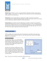
Proportional pressure controller Introduction Negative Logic is defined as a maximum command level (all bits are logic high) controlling a minimum pressure output. For example, in a 4-bit system, a 1111 digital signal would correspond to zero psi and a 0000 digital signal would correspond to the maximum pressure. Sinking Input requires the digital voltage to be supplied by the controller connected to the input of the PPC. A command signal must be supplied by the external controller to the digital input connections. The PLC "drives" the PPC, by which a digital input (as opposed to analog) will...
Open the catalog to page 7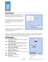
The Logic Monitor Signal provides digital feedback to confirm that the PPC has achieved the correct pressure. The LMS provides standard logic levels such as TTL (5V) or 24 VDC. With the TTL option, when correct pressure is achieved, the LMS outputs a logic 1, (5 VDC). When the PPC is working, (Fill or Exhaust valve is in operation) the LMS outputs a logic 0, 0 VDC. Figure 2 shows how to wire the LMS to a controller’s TTL input. The LMS provides a simple "go/no go" signal back to the controlling device. The LMS may also be used to turn on an L.E.D. for remote indication. COMMON (GREEN) There also...
Open the catalog to page 8
Proportional Pressure Controller Consult “Precautions” page 94 before use, installation or service of MAC Valves
Open the catalog to page 9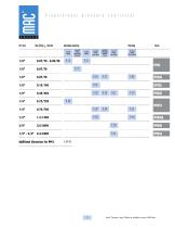
Proportional pressure controller Flow [Max] Cv / Nl/min Individual mounting base mount base moun covered analog covered analog with remote digital transducer Additional dimensions for PPC's P 89-93 Consult 'Precautions' page 94 before use, installation or service of MAC Valves.
Open the catalog to page 10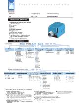
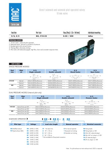
Port size Flow [Max][Cv] Individual mounting Covered Analog OPERATIONAL BENEFITS 1. Reliable operahifi, using Iwo MAC 24 Series v-i ih balanced popper. 6. Accurate pressure control. P. Can be slond aline -it used in combination v-iih cur remete air sandwich regulators. 10. Anal-ig command signal and -output. BASIC MODEL Porting SIDE PORTS A 1/8" NPTF B 1/8" BSPPL c 1/8" BSPTR BOTTOM PORTS D 1/8" NPTF £ 1/8" BSPPL f 1/8" BSPTR O Bottom port O-ring Mount OFeedback options Single Xducer/ Int. Sense (Pressure) Single Xducer/ Ext. Sense (Pressure) Dual Xducer/ ©Pressure reference ©Overall accuracy...
Open the catalog to page 11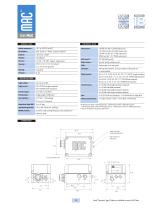
PNEUMATIC DATA Ambient temperature : Supply voltage : Supply current : Command signal : Command type : Input impedance : Analog Monitor Signal (AMS) : Logic Monitor Signal (LMS) : EMI/RFI protection : 0 to 10V or 4 to 20mA Single-ended or differential 4.99 kQ ± 1.0% (voltage) Common mode and high frequency noise reduction for electrical inputs * 30 PSI maximum inlet for 15 PSI output pressure - 2 BAR maximum inlet for 1 BAR output pressure -15 PSI maximum inlet for 2 PSI and 4 PSI output pressure - 1 BAR maximum inlet for 0.13 BAR output pressure ** Vacuum inlet should not exceed 25"/635 mm HG...
Open the catalog to page 12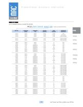
LIST OF AVAILABLE SIGNAL & CONNECTOR OPTIONS . CAA-AX 4-20mA SINGLE NONE NONE 3-PIN - CAA-DX 4-20mA SINGLE NONE NONE 3-PIN MICRO - CAA-GX 4-20mA SINGLE NONE NONE 3-WIRE GROMMET - BAA-HX 0-10V DIFFERENTIAL NONE NONE 4-WIRE GROMMET - DAA-HX 4-20mA DIFFERENTIAL NONE NONE 4-WIRE GROMMET DIFFERENTIAL NONE DIFFERENTIAL NONE DIFFERENTIAL NONE DIFFERENTIAL NONE DIFFERENTIAL NONE DIFFERENTIAL NONE DIFFERENTIAL NONE DIFFERENTIAL NONE DIFFERENTIAL NONE DIFFERENTIAL NONE DIFFERENTIAL NONE DIFFERENTIAL NONE Consult "Precautions" page 94 before use, installation or service of MAC Valves.
Open the catalog to page 13All MAC Valves Europe Inc catalogs and technical brochures
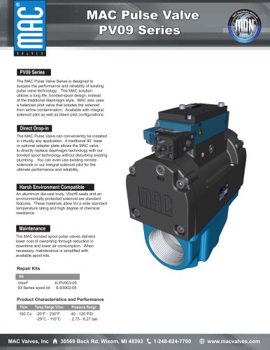 MAC PV09
3 Pages
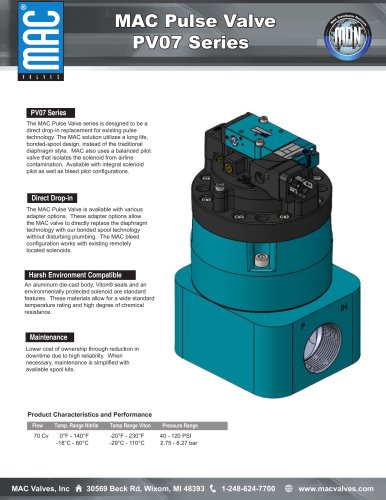 MAC PV07
2 Pages
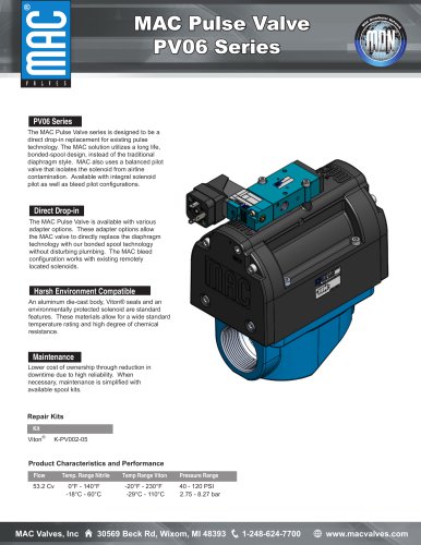 MAC PV06
3 Pages
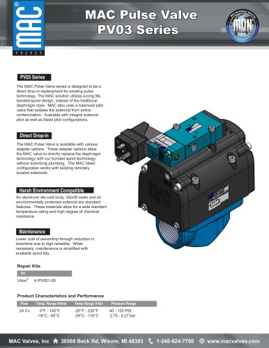 MAC PV03
3 Pages
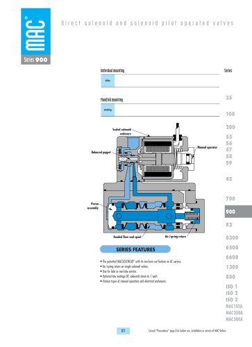 900 Series
10 Pages
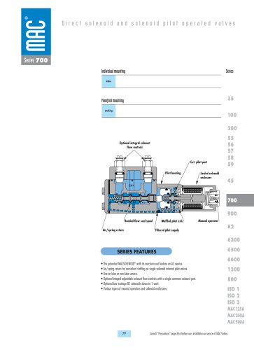 700 Series
10 Pages
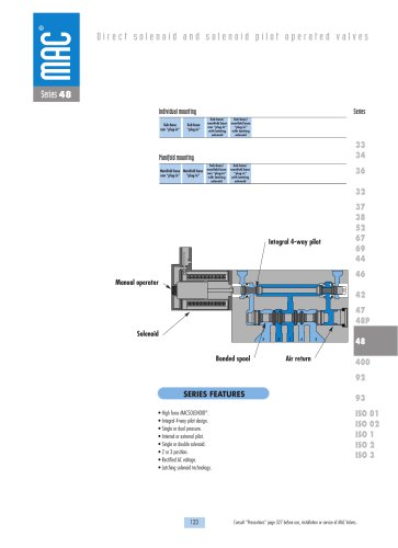 48 Series
13 Pages
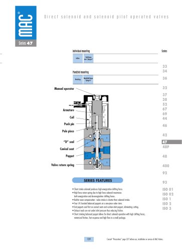 47 Series
11 Pages
 46L Series
20 Pages
 46 Series
15 Pages
 45 Series
18 Pages
 1600 Series
3 Pages
 44 Series
5 Pages
 43 Series
2 Pages
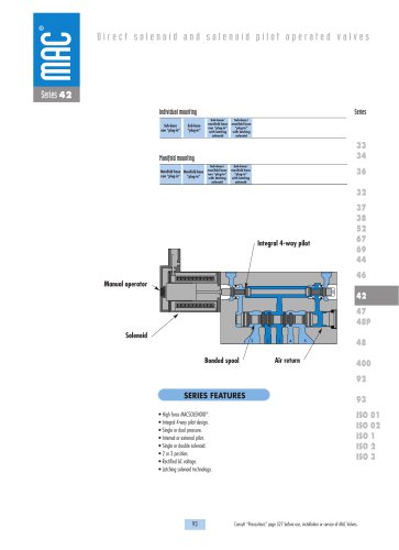 42 Series
13 Pages
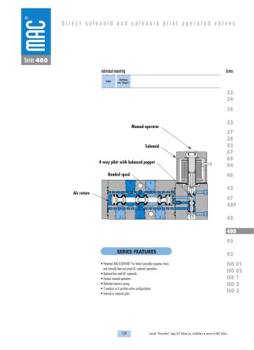 400 Series
10 Pages
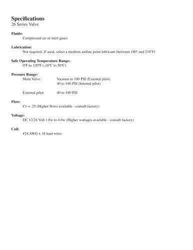 26 Series
9 Pages
 24 Series
24 Pages
 CURRENT TECHNOLOGY
359 Pages
 New Technology
277 Pages
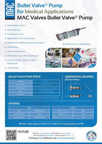 Bullet Valve® Pump
1 Page