Mecron® Cannulated Screw System and Chronoceptor™
1 /28Pages

Mecron® Cannulated Screw System and Chronoceptor™
1 /28Pages
Catalog excerpts

Mecron® Cannulated Screw System and Chronoceptor™ Surgical Technique This surgical technique applies only to the U.S. Chronoceptor™ e Surgical Techniqu (See Page 1
Open the catalog to page 1
Caution Federal law restricts this device to sale by or on the order of a physician. Caution The following product descriptions contain detailed information on the recommended procedure (and associated surgical techniques) for Merete® implants and instruments. Training in the correct handling of implants and instruments is only to be executed by an authorized Merete representative.
Open the catalog to page 2
Table of contents 1. Description 4 1.1. Intended Purpose 6 1.2. Indications 6 1.3. Contraindications 6 1.4. MRI Safety Information 7 2. General Information 7 3. Surgical Techniqu
Open the catalog to page 3
Mecron® Cannulated Screw System/Chronoceptor™ Description 1. Description The Mecron® Cannulated Screw System consists of headed and headless bone screws (Figure 1) made from TiAl6V4 ELI. Screws are available in diameters from 2.0 mm through 4.0 mm and overall lengths from 8 mm through 50 mm (Table 1). Table 1: Available Screw Dimensions. The Headed and Headless screws are color-coded according to diameter. Screw dia. Size in mm Figure 1: Headed (left) and headless (right) screws. Example illustration for 4.0 mm (gold). State-of-the-art design features Headed Screw Designed with a smooth curvature...
Open the catalog to page 4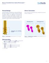
Mecron® Cannulated Screw System/Chronoceptor™ Description Thread Design Driver Connection The thread design is optimized by an ideal pitch differential between the threads of the head and shaft that keeps the distal threads from stripping through premature compression (Figure 4). Additionally, a reduced core diameter and increased thread depth maximizes pull-out resistance by maximizing the screw/bone interface. Each tip has three cutting flutes for self-drilling and self-tapping properties to reduce insertion torques during surgery. Driver connections are self-retaining for hexalobe driver sizes...
Open the catalog to page 5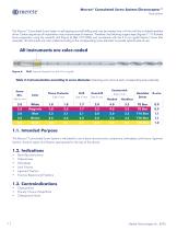
Mecron® Cannulated Screw System/Chronoceptor™ Description The Mecron® Cannulated Screw System is self-tapping and self-drilling and may be inserted over a K-wire with the included hexalobe driver. Certain sequences of implantation may improve ease of insertion. Therefore, the following surgery steps (Figures 7-11) illustrate bone preparation using the overdrill, drill (Figure 6) (Ref. CH15006) and countersink with the 4.0 mm (gold) Mecron® screw (this example). All instruments are color-coded according to the corresponding screw diameter to provide optimal ease-of-use. Drill. Example illustration...
Open the catalog to page 6
Mecron® Cannulated Screw System/Chronoceptor™ General Information 1.4. MRI Safety Information Risk of injury due to alternating magnetic fields: Merete GmbH has not authorized the use of MRI examinations in conjunction with the components described in these instructions for use. Conduct an individual risk-benefit analysis for each patient. Check whether other imaging procedures can be used to achieve the desired diagnostic aims. 2. General Information Warnings Use of damaged or defective implants/instruments. Risk of injury due to premature implant/instrument failure! Implants/Instruments with...
Open the catalog to page 7
3.1. Surgery Steps (Examples: Headed/Headless screws)10 3.2. Chronoceptor™12 3.3. Implanting the Mecron® Cannulated Screw System
Open the catalog to page 9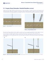
Mecron® Cannulated Screw System/Chronoceptor™ Surgical Technique 3.1. Surgery Steps (Examples: Headed/Headless screws) Position the K-wire (Ref. CK12215) across the fracture or fusion site (Figure 7). Confirm accurate K-wire placement and appropriate depth under direct visualization or fluoroscopy. Slide the Length Gauge (Ref. AI14001) over the K-wire (Figure 8). The measurement on the length gauge shows the depth of the K-wire in the bone and indicates the appropriate screw length. K-wire insertion. Position across fracture or fusion site. Figure 8: Screw length determination. Screw length determination...
Open the catalog to page 10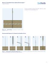
Mecron® Cannulated Screw System/Chronoceptor™ Surgical Technique Use the cannulated Countersink (CH15027, Table 2) to create a recess for the screw head (Figure 10). Figure 10: Countersinking. Countersinking for headed or oblique compression screws. Recommended Sequence for Headed and Headless Screws Figure 11: Surgery steps for headed and headless screws. With 1) K-wire placement, 2) length gauge, 3) overdrill, 4) drill, 5) countersink and 6) screw insertion. Headless screws are generally countersunk after the screw length is determined.
Open the catalog to page 11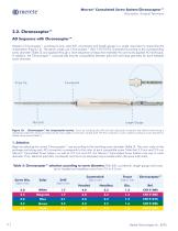
Mecron® Cannulated Screw System/Chronoceptor™ Description /Surgical Technique 3.2. Chronoceptor™ AO Sequence with Chronoceptor™ Merete’s Chronoceptor™ combines K-wire, pilot drill, countersink and length gauge in a single instrument to streamline the implantation (Figure 12). The sterile, single-use Chronoceptor™ (Ref. CH15101S) is selected according to the corresponding screw diameter (Table 3) and applied through a short sequence of steps that resemble the commonly applied AO technique. In addition, the Chronoceptor™ automatically ensures compatibility between pilot drill and head geometry...
Open the catalog to page 12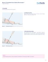
Mecron® Cannulated Screw System/Chronoceptor™ Surgical Technique 2. Assembly Load the appropriate size Chronoceptor™. 3. Guided Insertion Position trocar tip over the fracture or fusion site and slowly advance it under power (Figure 13). Positioning trocar tip. Drilling the first cortex with the trocar tip. 4. Pilot Hole Generation Stop advancing the Chronoceptor™ once the far cortex is breached (Figure 14) with the drill. This should be represented by slight resistance while the drill pushes through the far cortex. Pilot hole generation. Drill until the second cortex is breached. NOTE It may...
Open the catalog to page 13
Mecron® Cannulated Screw System/Chronoceptor™ Surgical Technique 5. Length Measurement Without advancing the trocar and drill, manually slide the handle forward until the countersink reaches cortical bone (Figure 15). The ratcheting mechanism advances in 2 mm increments and indicates the corresponding screw length along the subjacent laser mark. Next, obtain the reading from the handle once the final position is reached to select the correct screw length. Note that a reading may also be obtained from the Chronoceptor™ after the pilot hole and countersink recess are created and the Chronoceptor™...
Open the catalog to page 14All Merete catalogs and technical brochures
 BioBall System Catalogue
24 Pages
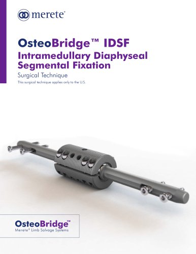 OsteoBridge™ IDSF
48 Pages
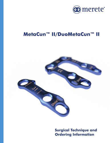 MetaCun II and Duo MetaCun II
16 Pages
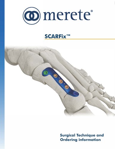 SCARFixTM
12 Pages
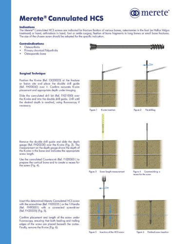 Merete Cannulated HCS
2 Pages
- Arthrodesis nail
- Metallic intramedullary nail
- Femoral stem
- Femoral intramedullary nail
- Acetabular prosthesis
- Titanium intramedullary nail
- Cementless femoral stem
- Cementless acetabular prosthesis
- Hip prosthesis
- Tibial intramedullary nail
- Femoral head prosthesis
- Non-absorbable bone staple
- Primary hip prosthesis
- Humeral intramedullary nail
- Revision acetabular prosthesis
- Revision hip prosthesis
- Epiphysis bone staple