- Catalogs
- Modus Medical Devices
- Modus QA - White Paper - MRID3D
Modus QA - White Paper - MRID3D
1 /28Pages

Modus QA - White Paper - MRID3D
1 /28Pages
Catalog excerpts
Measuring Geometric Distortion with Sub-Millimeter Accuracy in MRgRT QA: A Lighter, Faster, Single Acquisition, Large Field-Of-View Full 3D Approach with Simple Workflow Using the Harmonic Analysis Method WHITE PAPER Executive Summary The use of Magnetic Resonance Imaging (MRI) for guidance has expanded from research to clinical applications in the past decade. While MRI has many advantages related to image quality, image geometric distortion due to vendor design trade-offs and limitations dictated by cost and patient considerations require QA tools to ensure distortion is measured and acceptable limits are achieved to ensure accuracy of treatment. Advanced and demanding applications (Diffusion Weighted Imaging, Head and Neck Stereotactic Radiosurgery, MRI Guided Neurosurgery) require submillimeter accuracy. The factors which affect MRI Geometric Image Distortion are reviewed, as well as the tools that can be used to quantify distortion. A recommended method for measuring a full 3D distortion vector field using a lighter weight, large field of view hollow boundary phantom utilizing the harmonic analysis approach to achieve sub-millimeter accuracy (error < 0.1mm) is presented.
Open the catalog to page 1
Legal & Copyright Notice Information in this white paper is subject to change without notice. No part of this white paper may be reproduced in any form without the written permission of Modus Medical Devices Inc (Modus QA). Copyright ©2021 Modus Medical Devices Inc. All rights reserved. QUASAR™ and the QUASAR™ logo are trademarks of Modus Medical Devices Inc. Modus QA reserves the right to make any changes without further notice to any products herein. Modus QA makes no representation, warranty or guarantee regarding the suitability of its products for any particular purpose, nor does Modus QA...
Open the catalog to page 2
2020 Modus Medical Devices Inc. All rights reserved.
Open the catalog to page 3
1. Introduction Over the last decade, Magnetic Resonance Guided Radiation Therapy (MRgRT) has received considerable and increasing interest in the Cancer Research and Clinical Treatment community for several compelling reasons: 1. The utility of Magnetic Resonance Imaging (MRI) for high contrast patient, tumor, and organ registration with no additional ionizing radiation from the imaging modality. 2. The ability to provide real time motion tracking of moving tumors with exquisite soft tissue contrast to see what is being treated, which eliminates the need for an Internal Target Volume (ITV) around...
Open the catalog to page 4
A review of the factors which affect MRI spatial accuracy, and what can be done to manage and measure it, follows. 2. Technical Background 2.1. Formation of Magnetic Resonance Signal Unlike X-Ray, CT (kV or MV), Ultrasound, PET, SPECT and other related imaging modalities, MRI does not use projection, reflection, emission, or refraction mechanisms found in optical imaging methods, where acceptable spatial accuracy is normally assumed. MRI relies on a technique that exploits the interaction of three distinct non-ionizing static and time varying magnetic fields with atomic elements found within...
Open the catalog to page 5
with 1H, which is present in both water (H2O) and adipose tissue (containing H-C chains), both of which are abundant in human subjects. The second magnetic field B1 (or BRF) is a pulsed (limited time duration) time-varying magnetic field that corresponds to the Larmor Resonance Frequency, and falls in the Radio Frequency (RF) spectrum (13 MHz to 300 MHz) for Field Strengths between 0.35 T to 7 T. The B1 field is associated with RF coils, RF coil arrays, and the integrated RF Body Coil normally found in clinical MRI scanners which produce a primarily near-field magnetic field (within one wavelength...
Open the catalog to page 6
• MRI is based on assumption of linear encoding of position to frequency over FOV… with some design trade-offs • Linearity is high near gradient coil isocenter but falls off with increasing distance • Main effects: o Anatomical compression (S-I) o Anatomical dilation (A-P, R-L) o Aliasing • Field strength, sequence independent • Arises from vendors being forced to trade-off linearity for performance: shorter bore lengths (reduce claustrophobia) and larger bore diameter (to accommodate obesity) Figure 1. Gradient coil non-linearities are caused by design trade-offs to address economic concerns...
Open the catalog to page 7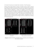
2.3. Vendor Corrections to Gradient Non-Linearities – Post-Processing All MRI vendors employ software correction of Gradient Coil Non-Linearity in 2D and 3D imaging, and apply the correction based on harmonic analysis of the uncorrected fields to produce a 2D and 3D distortion corrected image suitable for Diagnostic and Guided Treatment applications. Gradient coil designers use harmonic analysis methods, among other field target techniques, to design gradient coils. The gradient coil winding locations and patterns are optimized to satisfy boundary conditions which attempt to produce a 3D linear...
Open the catalog to page 8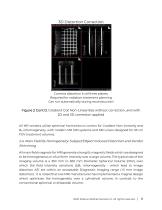
. Corrects distortion in all three planes: Required for radiation treatment planning Can run automatically during reconstruction Figure 2 Cont’d. Gradient Coil Non-Linearities without correction, and with 2D and 3D correction applied All MR vendors utilize spherical harmonics to correct for Gradient Non-Linearity and B0 inhomogeneity, with modern MR SIM systems and MR Linacs designed for 35 cm FOV treatment volumes. 2.4. Main Field B0 Homogeneity: Subject/Object Induced Distortion and Vendor Shimming All main field magnets for MRI generate strong B0 magnetic fields which are designed to be homogeneous...
Open the catalog to page 9
Conventional Magnet Design Imaging Volume Alternate Magnet Design Imaging Volume Figure 4. Representative Homogeneous Imaging Volumes for Conventional and Alternative Magnet and Gradient Designs Inhomogeneous regions at the edge of all manufacturers specified imaging volumes can be significant and may exceed acceptable distortion for precision MR Guided RT (<< 2mm of image distortion is required). Modern actively shielded high-field MRI magnet: coils and high uniformity central B0 field Figure 5. Main Field B0 Homogeneity on a Modern MR SIM System 2020 Modus Medical Devices Inc. All rights reserved....
Open the catalog to page 10All Modus Medical Devices catalogs and technical brochures
 PRODUCT CATALOG 2022
13 Pages
 QUASAR™ Catphan Shaker
2 Pages
 QUASAR™ GRID3D
2 Pages
 QUASAR™ MRID3D
2 Pages
 QUASAR MRID3D
2 Pages
 QUASAR IsoCenter Cube
2 Pages
 QUASAR Penta-Guide
2 Pages
 QUASAR? eQA
2 Pages
 QUASAR ADQ
2 Pages


