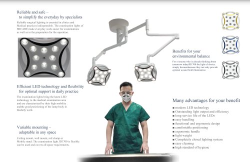
Catalog excerpts

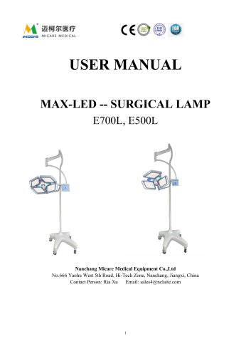
USER MANUAL MAX-LED -- SURGICAL LAMP E700, E500 Nanchang Micare Medical Equipment Co.,Ltd No.666 Yaohu West 5th Road, Hi-Tech Zone, Nanchang, Jiangxi, China Contact Person: Ria Xu
Open the catalog to page 1
CONTENT Cover -- -- -- -- -- -- -- -- -- -- -- -- -- -- -- -- -- ---------- -- -- ---------- 1 Main technical indicators and reference data ----------------------------2 Install and use ----------------------------------------------------------------3 Maintenance and repair -----------------------------------------------------4 Solutions to frequently asked questions -----------------------------------5 Storage and transportation --------------------------------------------------6 Normal operating environment --------------------------------------------7 Safe life...
Open the catalog to page 2
Nanchang Micare Medical Equipment Co.,Ltd . continuously strives to improve its products and therefore reserves the right to deliver product structures with features different from those described in this Manual without prior notice;However, Nanchang Micare Medical Equipment Co.,Ltd . warrants that these improvements comply with valid regulations and reserves all rights. 【 Abstract 】 You have just bought LED Surgical Lamps.We congratulate you on your choice and trust that you will be satisfied with its usage and performance. We recommend that you read this manual carefully before using the...
Open the catalog to page 3
questions you may have when using the lamp for the first time. If the power characteristics do not meet the requirements, the operating lamp will not exert its maximum efficiency, and will not ensure normal operation. The transportation risk of the equipment shall be borne by the consignee. Any dispute over loss or damage during transit must be declared in the presence of the carrier at the time of delivery and explained on the waybill. In no event shall packaging materials manufactured by the company be used for any purpose other than transportation. The instructions in this manual fully...
Open the catalog to page 4
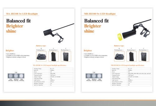
Warning: Appearing before certain operations, if these rules are violated, may damage the equipment and endanger personal safety. [Product appearance] Technical parameters Light Intensity at 1M (Lux) Color temperature (K) Spot diameter (mm) Color rendering index Temperature rise of surgeon's head (℃) Temperature rise in surgical field (℃) R9 Rendering Index Lighting depth (mm), L1+L2 At 60% The power supply voltage Input power (W) LED Quantity
Open the catalog to page 5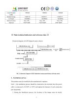
Lamp Diameter (MM) Radiant Energy Life Span Internal Camera Optional 【 Main technical indicators and reference data 】 Electrical diagram of LED Surgical Lamp is shown 2、Installation and use This product must be installed by the manufacturer's engineer. Note: 1, the installation process should be connected to the electrical line (the power cable is connected to AC220V or 110V) and tighten the fasteners of each connection part (important); 2. During the installation process, the levelness of the hanger must be s
Open the catalog to page 6
calibrated with a level (very important). 3. Before shadowless lamp is installed, the customer shall provide a 250V/10A switch/circuit breaker to complete the insulation protection of the line (important). 2.1 Hanger installation The minimum installation height of this product is 2.5m, please refer to the attached installation structure diagram when installing.As this product is a suspension bearing equipment, there are certain requirements for the bearing capacity of the ceiling or hanger. a) When there is a structural beam in the center of the ceiling of the operating room, a hanger can...
Open the catalog to page 7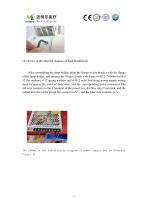
(As shown in the attached diagram of base installation) After assembling the lamp holder, align the flange on the bracket with the flange of the lamp holder, and connect the 4 holes firmly with 4 sets of M12×70 bolts (with 4 12 flat washers, 4 12 spring washers and 4 M12 nuts).Switching power supply wiring must recognize the color of each wire, and the corresponding color connection.The red wire connects to the L terminal of the power box, the blue ring N terminal, and the output red wire of the power box connect to V+, and the blue wire connects to V-. (As shown in the installation diagram...
Open the catalog to page 8
Shadowless lamp circuit diagram 2.3 Use of surgical lamp After the shadowless lamp is installed, electrification acceptance shall be carried out. 2.3.1 Scope of activities The bracket can rotate 360° back and forth around the lamp holder, the spring arm and straight tube can rotate 540° back and forth around the bracket, the spring arm can swing up and down 60°, and the lamp cap can rotate 540° around the ya tube joint.Each movement should be operated on the handle of the control box or lamp holder body. 2.3.2 Illumination adjustment 2.3.2.1 description The shadowless lamp control display...
Open the catalog to page 9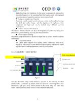
shadowless lamp, the brightness of other areas is automatically enhanced to ensure the brightness of the operating field.This function needs to be equipped with our company's supporting constant current source board. Lamp cap mutual control function Automatic control, mutual control and same control can be realized between the child and mother lamps, and the adjustment of brightness, color temperature and light spot can be realized under different operation requirements. Infrared remote control function The infrared remote controller can adjust the brightness of shadowless lamp, color...
Open the catalog to page 10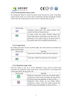
2.3.2.4 Synchronization control switch By clicking the button to realize the quick switch between the mode of automatic control and the mode of co-control.After switching the interface through the interface switch TAB, the synchronization control switch is automatically turned off. State that Automatic control mode: the control terminal only controls the head of the parent lamp Co-control mode: the control terminal controls the parent lamp and the child lamp at the same time. The parameters of the control board of the parent lamp in this control mode will be modified synchronously. 2.3.2.5...
Open the catalog to page 11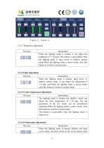
Figure 2, figure 3 2.3.2.7 Brightness adjustment The keys instructions When the lighting mode is normal, it can adjust the brightness of 1-10 gears.This button is unavailable when the lighting mode is deep cavity or shallow surface mode.When the lighting mode is mirror mode, click this button to switch to normal mode. 2.3.2.8 Spot adjustment The keys instructions When the lighting mode is normal, deep cavity or shallow surface mode, it can realize the adjustment of 1-4 light spot;When the lighting mode is mirror mode, click this button to switch to normal mode. 2.3.2.9 Color temperature...
Open the catalog to page 12All Nanchang Micare Medical Equipment catalogs and technical brochures
-
 MICARE Medical Loupes 2024
69 Pages
-
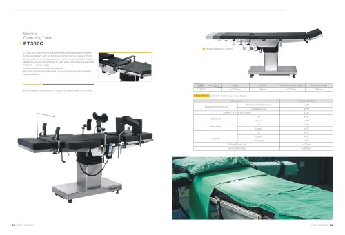
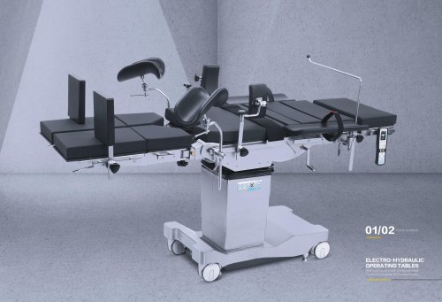 Surgical Tables Operating Tables
27 Pages
-
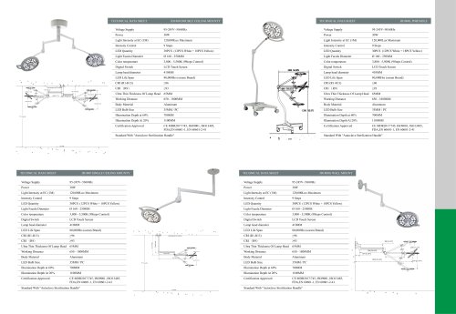
 power-led surgical light
6 Pages
-
 Invitation of Arab Health
1 Pages
-
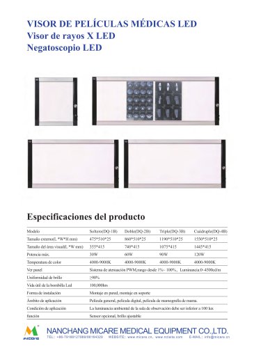
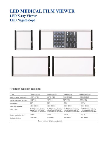 Led x ray film viewer
2 Pages
-
 Red Light Heat Lamp
8 Pages
-
 infrared therapy light
8 Pages
-
 Catalog of Medical Led Headlight
10 Pages
-
 Advantage of JD1800
1 Pages
-
 VET LED Surgical Lights
10 Pages
-
 Medical Surgical Loupes
1 Pages
-
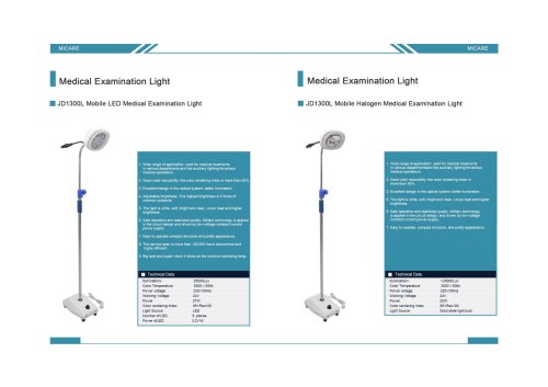 LED examination lamp JD1300L
1 Pages
-
 Infrared therapy lamp IL-001
8 Pages
-
 Surgical Operatin Table
27 Pages
-
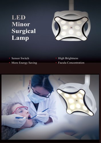 JD1700 Minor Surgical Light
4 Pages
-
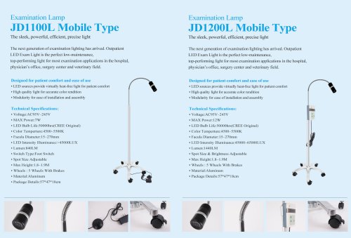
 Medical Examination Lamp
11 Pages
-
 Binocular Loupe
2 Pages
-
 X-ray Film Viewer
1 Pages