- Catalogs
- Nextremity Solutions
- InCoreTM Lapidus System
InCoreTM Lapidus System
1 /14Pages
InCoreTM Lapidus System
1 /14Pages
Catalog excerpts

InCoreTM Lapidus System Precision Guided Correction Surgical Technique
Open the catalog to page 1
InCore Lapidus System Precision Guided Correction • Tri-Planar Correction • Targeting Guide is intended to aid and stabilize angular/rotational correction in all three planes (transverse, sagittal and frontal plane) • Fully Guided • Post and Targeting Guide utilize anatomical land marks to facilitate fixation placement • Angular correction of the metatarsal facilitated and maintained by the targeting guide • Solid Intermedullary Construct • Solid 5.9mm Titanium Post provides large surface area engagement in the cancellous bone of the medial cuneiform • Headless compression screws thread directly...
Open the catalog to page 2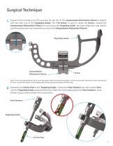
Prepare instrumentation by first ensuring the top line of the Compression-Distraction Fixture is aligned with the start line of the Targeting Guide. The T10 Driver is used to rotate the Screw, causing the Compression-Distraction Fixture to travel along the Targeting Guide. Improper alignment may restrict potential distraction and compression travel of the Compression-Distraction Fixture. Targeting Guide CompressionDistraction Fixture NOTE: The InCore Disposable Kit will come pre-assembled. After removing from package, confirm Compression-Distraction Fixture is positioned at “Start”. Ensure Post...
Open the catalog to page 3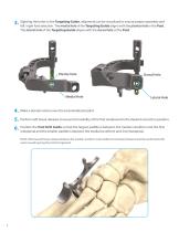
Sighting the holes in the Targeting Guide, alignment can be visualized to ensure proper assembly and left/right foot selection. The medial hole of the Targeting Guide aligns with the plantar hole in the Post. The lateral hole of the Targeting Guide aligns with the dorsal hole of the Post. Plantar Hole Medial Hole Dorsal Hole Lateral Hole Make a dorsal incision over the tarsometatarsal joint. Perform soft tissue releases to ensure full mobility of the first metatarsal to the desired correction position. Position the Post Drill Guide so that the largest paddle is between the medial cuneiform and...
Open the catalog to page 4
Before placing a 2mm K-wire, loosely place the K-wire into the Post Drill Guide and observe the angle of the K-Wire to be both parallel to TMT joint and in the middle of the long axis of the medial cuneiform. The K-wire will generally be placed dorsal-lateral to plantar medial. Adjust as necessary and place K-wire through the Post Drill Guide and into the bone. NOTE: If planning to cut the cuneiform for bone preparation, you may consider making cut prior to placing K-wire. Remove the Post Drill Guide, leaving the 2mm K-wire in the bone. NOTE: The guide is configured to aid in placing the K-wire...
Open the catalog to page 5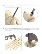
Insert the 5.9mm Post Reamer over the 2mm K-wire and drill until the depth line on the drill bit is at or just below bone surface. 10. Insert the Post and Targeting Guide Assembly into the previously reamed hole located in the medial cuneiform. Fully seat the Post into the bone ensuring the Targeting Guide depth lines are at or just below bone surface. NOTE: Light malleting may be required to fully seat post.
Open the catalog to page 6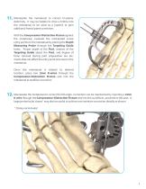
the metatarsal to correct tri-planar deformity. It may be helpful to drive a K-Wire into the metatarsal to be used as a joystick to gain additional frontal plane correction. With the Compression-Distraction Fixture against the metatarsal, evaluate the anticipated screw entry points on the metatarsal by placing the Depth Measuring Probe through the Targeting Guide holes. Proper depth of the Post, rotation of the Targeting Guide about the Post, and degree of bone removal during joint preparation are elements that can affect the entry point of screws in the metatarsal. Once the metatarsal is rotated...
Open the catalog to page 7
13. Using the T10 driver, turn the Screw in the Compression-Distraction Fixture counter-clockwise to distract the 1st tarsometatarsal joint. NOTE: Soft tissue release may be required to achieve desired distraction and optimal visualization. 14. After desired distraction is achieved, continue to prep the joint with curettage, microfracture and other preferred bone preparation methods. 15. Following bone preparation, turn the Screw clockwise to compress the metatarsal to the medial cuneiform. While compressing, ensure metatarsal base does not deflect plantarly and that the Post does not shift dorsally....
Open the catalog to page 8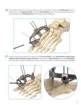
16. Once desired correction is achieved and secured in compression, place the Drill Bushing into the medial hole in the Targeting Guide. Ensure the Drill Bushing chosen is the longest bushing that will fully seat against the Targeting Guide without touching the metatarsal. 17. Ensure the post is fully seated, then introduce the 3.6mm Drill Bit into the Drill Bushing. Do NOT begin drilling until the Drill Bit engages the bone. Fully seat the 3.6mm Drill Bit against the Drill Bushing (up to the step on the bit) to ensure drill creates a continuous tunnel of an appropriate length to the Post.
Open the catalog to page 9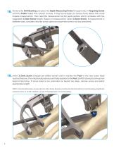
Bushing the Depth Measuring Probe through holes in Targeting 18. Remove the Drillmakes firmand placeto bone. It may be necessary to remove bone debris thatGuide until the Probe contact could impede measurement. Then read the measurement at the guide surface which correlates with the suggested 3.5mm Screw length. Based on measurement, select 3.5mm Screw. If measurement is between sizes, consider a shorter screw option to ensure the screw is not too prominent. 19. Insert 3.5mm Screw through pre-drilled tunnel until it reaches the Post or the rear screw head reaches the bone. Then rotationally advance...
Open the catalog to page 10
process of choosing the 20. Repeat theplacement for the lateral correct Drill Bushing, drilling, measuring for 3.5mm Screw length and screw screw. 21. To aid in removing K-Wires, slightly reduce the compression by turning Compression-Distraction Fixture Screw counter-clockwise and remove all K-wires. Twist Post Fastener to release from Post and remove Targeting Guide. 22. Once both 3.5mm Screws are locked into the Post, thread the Post Plug Screw into the top of the Post. 23. Close in the usual manner. 10
Open the catalog to page 11
Revision Surgical Technique 1. 2. Locate the Post in the cuneiform and clear bone to gain access. Remove the Post Plug Screw using the T10 InCore Lapidus Driver. Make a dorsal incision over the tarsometatarsal joint. Align the Revision Guide with the Post. Place the Revision Post Fastener through the Revision Guide and thread onto the Post. Hand tighten to stabilize the assembly.
Open the catalog to page 12All Nextremity Solutions catalogs and technical brochures
 Nextra® CH
12 Pages
 InCore TMT System
14 Pages
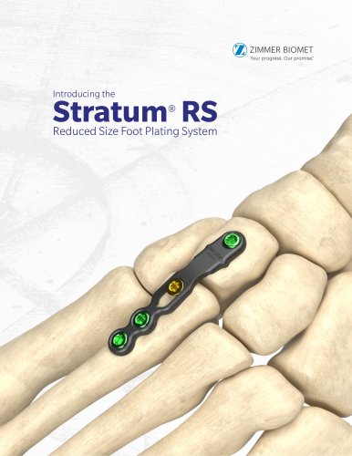 Foot Plating System
12 Pages
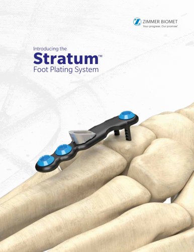 Foot Plating System
12 Pages
- Bone plate
- Arthrodesis plate
- Osteotomy plate
- Locking arthrodesis plate
- Locking osteotomy plate
- Foot arthrodesis plate
- Arthrodesis screw
- Proximal osteotomy plate
- Foot arthrodesis screw
- Foot osteotomy plate
- Headless arthrodesis screw
- Non-locking osteotomy plate
- Hallux valgus osteotomy plate
- Metatarsal bone osteotomy plate
- Forefoot arthrodesis plate