- Catalogs
- Ocean Insight
- HR2000+
HR2000+

HR2000+
The Ocean Optics HR2000+ Spectrometer is a compact and flexible system designed for high spectral response and optical resolution. It is suitable for OEM integration and connects to PCs via USB 2.0 or RS-232. The spectrometer features a high-sensitivity 2048-element CCD array with enhanced optical sensitivity.
The HR2000+ offers an optical resolution ranging from 0.035 to 6.8 nm, supports 14 gratings and 6 slit widths, and includes a 14-bit, 5MHz A/D converter. It has integration times from 1 ms to 65 s and multiple triggering modes. Additional features include an onboard pulse generator, GPIO, analog interface, and EEPROM storage for calibration coefficients. It is CE certified.
The spectrometer requires 220 mA at +5 VDC, with dimensions of 148.6 mm x 104.8 mm x 45.1 mm and a weight of 570 g. It uses an asymmetric crossed Czerny-Turner design with a 101 mm focal length. The dynamic range is 2 x 10⁸ with a signal-to-noise ratio of 250:1.
The HR2000+ includes a 30-pin connector for interfacing with external products, featuring RS232 Tx/Rx, GPIO, and analog input/output. It supports various triggering modes, including external hardware and software triggers.
The spectrometer's pixel definition includes optical black and active pixels, with programmable timing signals for synchronization with external devices.
The HR2000+ supports multiple triggering modes: Normal, Software Trigger, External Synchronous Trigger, External Hardware Level Trigger, and External Hardware Edge Trigger.
Includes a 13-bit ADC for analog input and a 9-bit DAC for analog output, with 10 programmable digital I/O pins.
Supports USB 2.0 for fast data transfer and RS-232 for standalone operation with external power.
Commands are sent via USB with specific byte formats for initializing the device, setting integration time, enabling strobe, and querying information.
Spectral data is acquired in bulk transfer mode with specific packet formats for USB communication.
Various trigger modes can be set by passing specific data values.
The spectrometer can query plug-in accessories, with data returned in binary format.
Supports I2C read and write operations for interfacing with peripherals, operating at 400KHz.
Controllable parameters are accessible through specific commands, affecting spectrometer performance.
Can read PCB temperature and manage irradiance calibration data from EEPROM.
Returns current operating information, including integration time and trigger mode.
Communicates via USB or RS-232, with commands sent as ASCII characters.
Includes commands for setting parameters like scan addition, pixel boxcar width, and integration time.
The Master HR2000+ drives the Master Clock Signal at 2.4MHz, used by other units.
Set in terms of Master Clock intervals to synchronize integration time with the External Trigger input.
A diagram illustrates a setup using three HR2000+ units, with connections for Laser Trigger In, Lamp Synch Out, and Q-Switch Trigger.
Catalog excerpts

HR2000+ Data Sheet Description The Ocean Optics HR2000+ Spectrometer includes the linear CCD-array optical bench, plus all the circuits necessary for spectrometer operation. The result is a compact, flexible system, with no moving parts, that's easily integrated as an OEM component. The HR2000+ spectrometer is a unique combination of technologies providing users with both an unusually high spectral response and high optical resolution in a small footprint. The electronics have been designed for considerable flexibility in connecting to various modules as well as external interfaces. The HR2000+ interfaces to PCs, PLCs and other embedded controllers through USB 2.0 or RS-232 communications. The information included in this data sheet provides detailed instructions on the connection and operation of the HR2000+. The detector used in the HR2000+ spectrometer is a high-sensitivity 2048-element CCD array from Sony, product number ILX511B. (For complete details on this detector, visit Sony’s web site at www.sony.com. Ocean Optics applies a coating to all ILX511 detectors, so the optical sensitivity could vary from that specified in the Sony datasheet). The HR2000+ operates from the +5V power, provided through the USB, or from a separate power supply and either a USB or RS-232 interface. The HR2000+ is a microcontroller-controlled spectrometer, thus all operating parameters are implemented through software interfacing to the unit. The HR4000 Breakout Box (HR4-BREAKOUT) is available from Ocean Optics for use with the HR2000+ Spectrometer. The HR4000 Breakout Box is a passive module that separates the signals from their 30-pin port to an array of standard features found on the HR2000+ Spectrometer.
Open the catalog to page 1
An optical resolution of ~0.035 to 6.8 nm (FWHM) A wide variety of optics available • 14 gratings • 6 slit widths • 6 optical filters, 1 order-sorting filter Electrical Performance • 14 bit, 5MHz A/D Converter • Integration times from 1 ms to 65 s 4 or 5 triggering modes (depending on firmware) Embedded microcontroller allows programmatic control of all operating parameters and Standalone operation • USB 2.0 480Mbps (High-speed) & 12 Mbps (Full speed) • RS232 115Kbaud • Communication Standard for digital accessories (I2C) Onboard Pulse Generator • 2 programmable strobe signals for triggering...
Open the catalog to page 2
Specifications Specifications Absolute Maximum Ratings: VCC Voltage on any pin Physical Specifications: Physical Dimensions Weight Power: Power requirement (master) Supply voltage Power-up time 220 mA at +5 VDC 4.5 – 5.5 V ~5s depending on code size Spectrometer: Design Focal length (input and output) Input Fiber Connector Gratings Entrance Slit Detector Filters Spectroscopic: Integration Time Dynamic Range Signal-to-Noise Readout Noise (single dark spectrum) Resolution Stray Light Spectrometer Channels Asymmetric crossed Czerny-Turner F/4, 101 mm SMA 905 to single-strand optical fiber (0.22...
Open the catalog to page 3
Mechanical Diagram Figure 1. HR2000+ Outer Dimensions 4
Open the catalog to page 4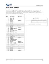
Electrical Pinout Listed below is the pin description for the HR2000+ Accessory Connector (J3) located on the front vertical wall of the unit. The connector is a Pak50TM model from 3M Corp. Headed Connector Part# P50-030P1-RR1-TG. It mates with Part # P50-030S-TGF (requires two: 1.27mm (50 mil) flat ribbon cable: Recommended 3M 3365 Series). Description RS232 Rx RS232 Tx GPIO(2) V5_SW Ground I2C SCL GPIO(0) I2C SDA GPIO(1) External Trigger In GPIO(3) VCC, VUSB or 5Vin Reserved VCC, VUSB or 5Vin Reserved GPIO(4) Single Strobe GPIO(5) Reserved Continuous Strobe SPI Chip Select GPIO(6) Analog In...
Open the catalog to page 5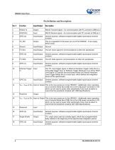
RS232 Transmit signal – for communication with PC connect to DB9 pin 2 RS232 Receive signal – for communication with PC connect to DB9 pin 3 General purpose, software-programmable digital input/output (channel number) This is a regulated 5-Volt power pin out of the HR2000+. It can supply 50mA (max). The I2C Clock signal for communications to other I2C peripherals General purpose, software-programmable digital input/output (channel number) The I2C Data signal for communications to other I2C peripherals General purpose, software-programmable digital input/output (channel number) The TTL input trigger...
Open the catalog to page 6
Pin Definition and Descriptions (Cont’d) Pin # Continuous Strobe The Analog Out is a 9-bit programmable output voltage with a 0-5 Volt range. Lamp Enable A TTL signal that is driven Active HIGH when the Lamp Enable command is sent to the spectrometer General purpose, software-programmable digital input/output (channel number) General purpose, software-programmable digital input/output (channel number) General purpose, software-programmable digital input/output (channel number) TTL output signal used to pulse a strobe that is divided down from the Master Clock signal General purpose, software-programmable...
Open the catalog to page 7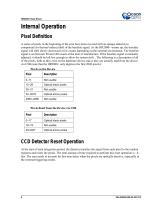
Internal Operation Pixel Definition A series of pixels in the beginning of the scan have been covered with an opaque material to compensate for thermal induced drift of the baseline signal. As the HR2000+ warms up, the baseline signal will shift slowly downward a few counts depending on the external environment. The baseline signal is set between 90 and 140 counts at the time of manufacture. If the baseline signal is manually adjusted, it should be left low enough to allow for system drift. . The following is a description of all of the pixels, both as they exist on the hardware device and as...
Open the catalog to page 8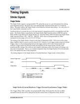
Timing Signals Strobe Signals Single Strobe The Single Strobe signal is a programmable TTL pulse that occurs at a user-determined time during each integration period. This pulse has a user-defined High Transition Delay and Low Transition Delay. The pulse width of the Single Strobe is the difference between these delays. It is only active if the Lamp Enable command is active. Synchronization of external devices to the spectrometer's integration period is accomplished with this pulse. The Strobe Delay is specified by the Single Strobe High Transition Delay (SSHTD) and the Pulse Width is specified...
Open the catalog to page 9All Ocean Insight catalogs and technical brochures
 NIRQuest+ NIR Spectrometers
2 Pages
 OCEAN SR SERIES
37 Pages
 Ocean ST Microspectrometer
2 Pages


Archived catalogs
 Flame Spectrometer
2 Pages
 USB2000+
2 Pages
 USB4000
2 Pages
 HR4000
2 Pages
 Light Sources
20 Pages
 Sampling Accessories
26 Pages
 Spectrometers
58 Pages
 Jaz Modular Spectroscopy
18 Pages
 Fibers and Probes
22 Pages
- Windows software
- Protective glasses
- Laboratory rack
- LED light source
- Design software
- Treatment software
- Acquisition software
- Measurement software
- Benchtop spectrometer
- Safety glasses
- Compact light source
- Digital control unit
- Microscope light source
- Compact spectrometer
- Optical spectrometer
- Research spectrometer
- Spectrometer for the pharmaceutical industry
- NIR spectroscope