
- Catalogs
- ODU GmbH & Co. KG
- ODU-MAC® Blue-Line

- Products
- Catalogs
- News & Trends
- Exhibitions
ODU-MAC® Blue-Line
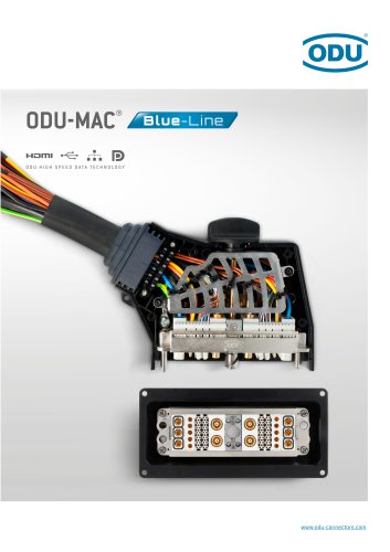
ODU-MAC® Blue-Line
- User-friendly assembly and removal of modules without tools.
- Available in four frame sizes with a maximum of 370 contacts per connector.
- High-performance with over 10,000 mating cycles.
- Customizable solutions for specific requirements.
- ODU TURNTAC®: Economical slotted contacts with high durability.
- ODU LAMTAC®: Lamella technology for high contact safety and low wear.
- Contacts retained using a clip principle for easy removal and replacement.
- Modules can be assembled with or without contacts at any process step.
- PCB termination modules offer a quick-change system for parts subject to wear.
- Operating temperature range: −40 °C to +125 °C.
- Protection class: IP67 for certain models.
- EMC shielding according to IEC standards.
- Spindle locking systems for secure connections with over 10,000 locking cycles.
- Various housing options including metal and plastic with different locking mechanisms.
- Contact Finishing: Gold-plated.
- Materials: Insulator made of thermoplastic according to UL 94, contact made of copper alloy.
- IEC 60664-1:2020: Operating voltage varies between 160 V to 550 V, with pollution degrees 2 and 3, and rated surge voltage up to 4,000 V.
- MIL Standards: Operating voltage up to 800 V, test voltage up to 2,400 V.
- IEC 61010-1:2010: Supply voltage from grid supply circuit (CAT.2) ranges from 150 V to 300 V, with test voltages up to 2,394 V AC.
- Mating Cycles: Minimum 10,000 cycles.
- Current-Carrying Capacity: Up to 25 A for certain modules.
- Solder Temperature: +260 °C for 30 seconds for PCB termination module.
- Frequency Range: 0 – 12 GHz for certain coax contacts.
- Insertion Loss: Detailed graphs provided for loss in dB across frequency ranges.
- Voltage Standing-Wave Ratio (VSWR): Graphs provided for VSWR across frequency ranges.
- Various modules and contacts are specified with part numbers, nominal and maximum continuous currents, and contact resistances.
- Modules are compatible with specific PCB termination modules and have detailed mechanical dimensions provided.
- Current load information is valid for single contacts or fully equipped modules, with load reduction recommended for connector systems.
- Crimping and removal tools are specified for various contact types.
Catalog excerpts
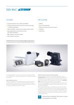
• Universal solution: fast, modular and flexible • Variety of locking options for plastic and metal housings • > 10,000 mating cycles • Clip-in assembly / removal of the modules without tools • Easy replacement of crimp-clip contacts, even when assembled • Wide range of transmission types • Ultra-compact connector Medical Test and measurement Military, security and communications Industrial Automotive ATTENTION: All shown connectors and cable assemblies are defined without breaking capacity (COC) according to IEC 61984:2008 (VDE 0627:2009-11). The majority of ODU-MAC® modules and contacts have...
Open the catalog to page 2
Clickable page numbers
Open the catalog to page 3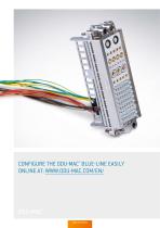
CONFIGURE THE ODU-MAC® BLUE-LINE EASILY ONLINE AT: WWW.ODU-MAC.COM/EN/ ODU-MAC® Table of contents
Open the catalog to page 4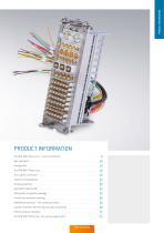
PRODUCT INFORMATION Your hybrid connection . . 18
Open the catalog to page 5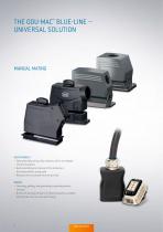
• Easy assembly using crimp contacts, which are clipped into the insulators • Quick assembly and removal of the modules in the frame without using tools • Removal of the contacts from the pin side • Centering, guiding, and grounding via guiding sockets and pins • Numerous housing versions in metal and plastic available with spindle, lever or push-pull locking
Open the catalog to page 6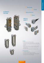
• Transmission of signals, power, high-current, high-voltage, HF signals (coax), compressed air, fluid, vacuum, data, and fiber optic • Additional option for the transmission of signals: separate PCB termination modules for effective contacting in the termination area • Very high contact density via the 2.4 mm grid (1 unit) • Up to 370 contacts per single-row connector • Proven ODU contact technology (turned / slotted contacts and contacts with lamella technology)
Open the catalog to page 7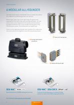
PRODUCT INFORMATION A MODULAR ALL-ROUNDER The flexible modular design of the ODU-MAC® Blue-Line enables the combination of different transmission types within one connector. Whether signal, power, high-current, high-voltage, HF signals (coax), compressed air, fluid, data, or fiber optic are being transmitted – all of the contact inserts can be integrated into the individual connector solution. For signal transmission, there is also a simple contacting option using PCB termination modules. The individual parts are supplied loose. There are various applications possible: from installation with...
Open the catalog to page 8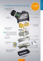
possible areas of application: manual mating or automatic docking PRODUCT INFORMATION THE MODULAR SYSTEM AT A GLANCE 2 10,000 mating cycles and more wide range of cable hood versions strain-relief plate contacts for solder, crimp, and PCB termination types of locking: spindle, lever, transverse or push-pull locking modules to choose from: signal, power, high-current, high-voltage, HF signals (coax), compressed air, fluid, vacuum, data, fiber optic, thermocouple and PCB termination spindle locking different spindle geometries pin frame Contacts with the clip principle that can be dismantled (see...
Open the catalog to page 9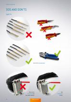
PRODUCT INFORMATION Use correct crimping tools! Never insert test probes into the contact sockets!
Open the catalog to page 10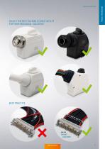
SELECT THE BEST SUITABLE CABLE OUTLET FOR YOUR INDIVIDUAL SOLUTION! BEST PRACTICE Use the ODU-MAC® strain relief! PRODUCT INFORMATION
Open the catalog to page 11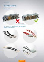
PRODUCT INFORMATION DOS AND DON’TS BEST PRACTICE Balancing is needed to avoid uneven mating and demating force! SELECT OUT OF A WIDE RANGE OF PRE-ASSEMBLED MODULES AND CONTACTS
Open the catalog to page 12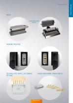
IDEAS Safety measurement solution! PARKING POSITION SEVERAL FIRST MATE, LAST BREAK OPTIONS ORDER ADDITIONAL SPARE PARTS! PRODUCT INFORMATION PRODUCT INFORMATION
Open the catalog to page 13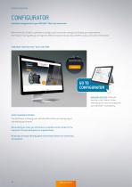
PRODUCT INFORMATION CONFIGURATOR Individual configuration of your ODU-MAC ® Blue-Line connection With the Product Finder it’s possible to configure your connection simply according to your requirements. The Product Finder guides you through the different choices step by step and offers many continuative information. CONFIGURE YOUR ODU-MAC ® BLUE-LINE HERE: GO TO CONFIGURATOR www.odu-mac.com takes you directly to the Product Finder, allowing you to start to configurate your ODU-MAC ® immediately. SELECT & REQUEST OFFERS You will receive a drawing and a detailed offer within one working day of...
Open the catalog to page 14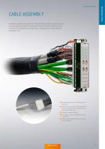
CABLE ASSEMBLY In addition to high quality connectors, ODU also offers complete system solutions including cable assembly. The advantage is that you receive the cable harness in an all-in-one solution from a single source. This greatly minimizes effort and installation time. C omplete solution from ODU with years of expertise State-of-the-art production facilities with 100 % end testing, high-voltage testing and component testing C ustomer-specific labeling P rototype, small series and high volume production W ide range of standard cables and accessories available PRODUCT INFORMATION PRODUCT...
Open the catalog to page 15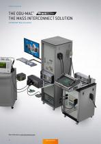
PRODUCT INFORMATION THE ODU-MAC® THE MASS INTERCONNECT SOLUTION with ODU-MAC ® Blue-Line modules More information: odu-interconnect.com 16
Open the catalog to page 16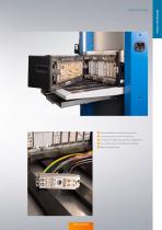
Easy assembly and removal of contacts C onstantly low transition resistance F lexibility through easy and fast configuration Free combination of the different modules High packing density PRODUCT INFORMATION PRODUCT INFORMATION
Open the catalog to page 17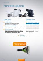
PRODUCT INFORMATION MANUAL MATING AUTOMATIC DOCKING © 4 TYPES OF LOCKING © 4 DOCKING FRAMES TO CHOOSE FROM Size Tolerance compensation radial: +/- 0.6 mm Tolerance compensation axial: min. 0.1 mm First, select your locking type by choosing between spindle, lever, transverse or push-pull locking. Then select the plastic or metal housing best suited to your requirements: cable hood, cable hood XXL, cable hood wide, RAPID or PUSH-LOCK housing. Depending on your requirements you choose between bulkhead mounted housing, surface mounted housing, cable-to-cable hood, PUSH-LOCK receptacles or recessed...
Open the catalog to page 18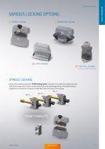
VARIOUS LOCKING OPTIONS SPINDLE LOCKING TRANSVERSE LOCKING LEVER LOCKING PUSH-PULL LOCKING (for ODU-MAC ® PUSH-LOCK housing) SPINDLE LOCKING Quick-action locking system with 10,000 locking cycles. If required, the simple front replacement set (spindle exchange set) enables a simple adjustment of the spindle geometry. The spindle locking is integrated in a module for installation in ODU-MAC® Blue-Line frames for housings. 360° 180° PRODUCT INFORMATION PRODUCT INFORMATI
Open the catalog to page 19All ODU GmbH & Co. KG catalogs and technical brochures
 ODU CARD
33 Pages
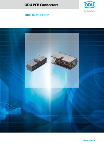 ODU MINI-CARD®
18 Pages
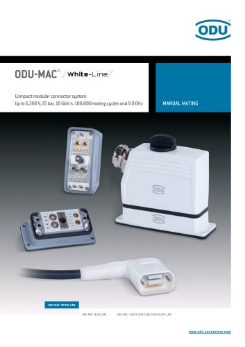 ODU-MAC® White-Line
184 Pages
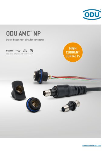 ODU AMC® NP
52 Pages
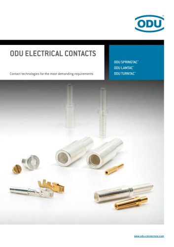 ODU ELECTRICAL CONTACTS
76 Pages
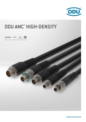 ODU AMC® HIGH-DENSITY
56 Pages
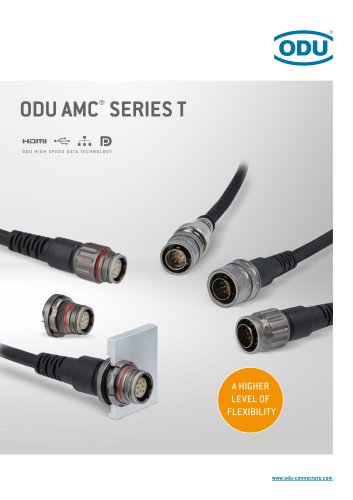 ODU AMC® SERIES T
88 Pages
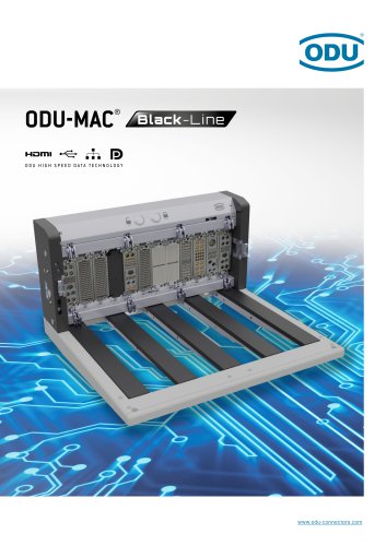 ODU-MAC® Black-Line
74 Pages
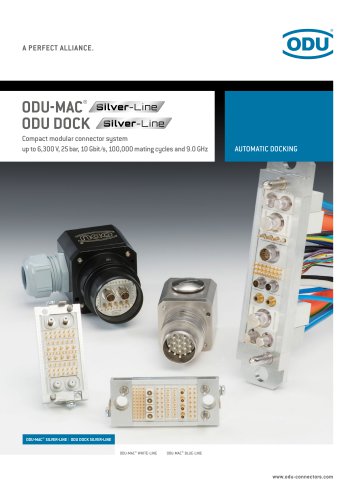 ODU-MAC® Silver-Line
206 Pages
 ODU EASY-CLEAN®
54 Pages
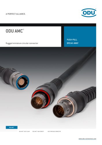 ODU AMC®
76 Pages
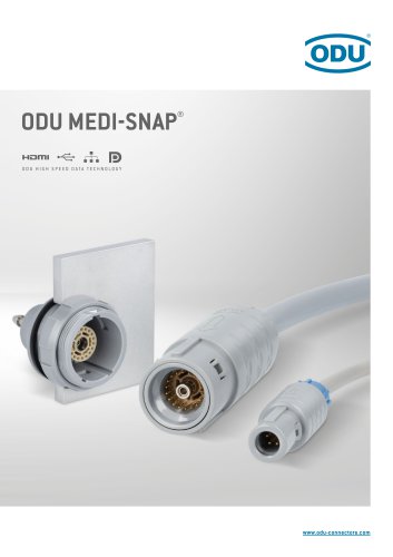 oDu MEDi-SnaP®
126 Pages
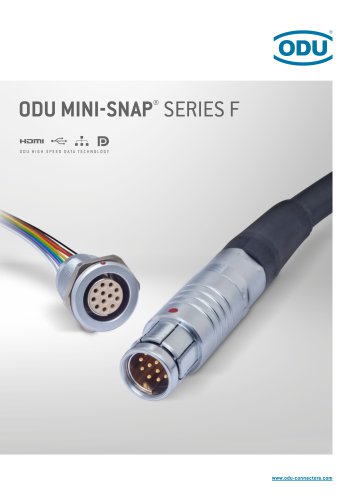 ODU MINI-SNAP® SERIES F
106 Pages
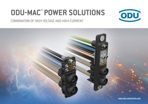 ODU-MAC® POWER SOLUTIONS
6 Pages