
Catalog excerpts

MINI IMPLANT
Open the catalog to page 1
CONTENT INDEX OVERVIEW PROSTHETIC IMPLANT LINES OVERVIEW PROSTHETIC PARALLEL IMPLANT Technical features Reference codes RATCHET CLEANING AND MAINTENANCE ACTIVE IMPLANT Technical features Reference codes SHORT IMPLANT Technical features Reference codes MINI IMPLANT Technical features Reference codes Insertion procedure PRELIMINARY INDICATIONS FOR SURGICAL INSTRUMENT USE SURGICAL TRAY - TRAY “IS” SURGICAL TRAY - TRAIY “IM” READING DEPTH NOTCHES AND SHARP DRILLS DRILL STOP IMPLANT CONNECTIONS FEATURES AND MEASURES IMPLANTS INSERTION PROCEDURE IMPLANT CONNECTION SCREWDRIVERS O-RING REPLACEMENT...
Open the catalog to page 2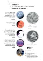
a surface with over 20 years of history CONSTANT OVER TIME The capacity of BWS® to retain fibrin, lets osteoblasts migrate from the bone to the implant surface and reproduce there, generating new bone in direct contact with the titanium (contact Osseointegration). Bone tissue grown in direct contact with the surface BWS® The process of sandblasting and acid etching the implant surface makes it possible to obtain optimal values of roughness creating the strongest fibrin adhesion to the surface and facilitating the bone healing process by significantly reducing the time. After the surface...
Open the catalog to page 3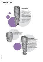
IMPLANT LINES PARALLEL IMPLANT Fixture with cylindrical body and a conical apex. Modulating the surgical procedure it is indicated in all bone types; even in the case of non-compact bone it is able to achieve a good primary stability. You can use it for any type of prosthetic restoration, screwed and cemented. Using the concept of platform switching allows you to better manage the soft tissue in the area of the implant – abutment interface, and reduce peri-implant bone resorption over time. SHORT IMPLANT Even if they are 6.0 mm length, allows the realization of surgical procedures without...
Open the catalog to page 4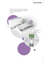
ORA Dental Implant GHBH endosseous implants are supplied in sterile packaging which, if undamaged, guarantees the implant is protected from external agents and, if stored correctly, their sterility. Protective implant cap supported by a titanium ring. (Surgical colour code) Transparent ampoule Protective closure screw cap. (Prosthetic colour code)
Open the catalog to page 5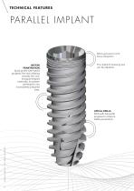
TECHNICAL FEATURES PARALLEL IMPLANT Micro-grooves to limit bone resorption. BETTER PENETRATION Spiral profile with hybrid progress: flat and radiating towards the root, triangular-shaped externally, for greater penetration into incompletely prepared sites. The implant’s screwing axis can be adjusted. APICAL DRILLS Drills with helicoidal progress to enhance stable penetration.
Open the catalog to page 6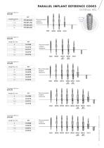
PARALLEL IMPLANT REFERENCE CODES INTERNAL HEX Diameter (Ø) mm Recommended surgical sequence
Open the catalog to page 7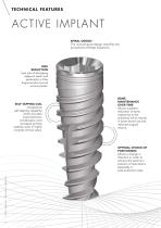
TECHNICAL FEATURES ACTIVE IMPLANT SPIRAL DESIGN The unusual spiral design simplifies the procedures of Ridge Expansion. RISK REDUCTION Less risk of damaging adjacent teeth and perforation of the lingual and/or buccal cortical plates. SELF-TAPPING COIL Exceptional self-tapping capability which provides improved bone condensation and increased primary stability, even in highly complex clinical cases. BONE MAINTENANCE OVER TIME Allows a greater reduction of bone osteotomy to be achieved, which results in lower bone loss and reduced surgical trauma. OPTIMAL CHOICE OF POSITIONING Allows a change...
Open the catalog to page 8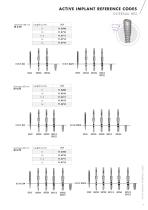
ACTIVE IMPLANT REFERENCE CODES INTERNAL HEX Length (L) mm
Open the catalog to page 9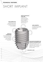
TECHNICAL FEATURES SHORT IMPLANT SELF-TAPPING COIL Self-tapping coil with double principle thread for increased contact with the bone and greater primary stability. BONE MAINTENANCE OVER TIME Polished coronal chamfer and implant collar are designed to better manage the biological width and maintain the level of bone over time. SPIRE GEOMETRY The geometry of the spire aids osseous healing, both qualitatively and quantitatively. IMPROVED PENETRATION Four wide cutting zones for greater penetration capacity and to gather bone fragments, therefore reducing compression. FACILITATES POSITIONING...
Open the catalog to page 10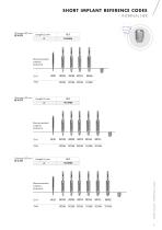
SHORT IMPLANT REFERENCE CODES INTERNAL HEX
Open the catalog to page 11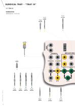
SURGICAL TRAY - “TRAY IS” REF TRAY IS DIMENSIONS 142x104 mm - h 61 mm IMPLANT DRIV INITIAL DRILL DRLNC
Open the catalog to page 12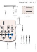
SURGICAL TRAY - “TRAY IS” COMPARTMENT INSIDE DRILL STOP
Open the catalog to page 13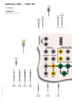
SURGICAL TRAY - “TRAY IM” IMPLANT DRIV INITIAL DRILL DRLNC
Open the catalog to page 14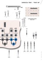
SURGICAL TRAY - “TRAY IM” (at choice) (at choice) (at choice) (at choice) COMPARTMENT INSIDE DRILL STOP
Open the catalog to page 15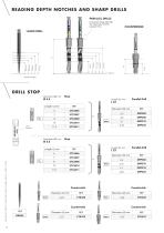
READING DEPTH NOTCHES AND SHARP DRILLS PARALLEL DRILLS Coloured rings identify the diameter of the surgical line LANCE DRILL DRILL STOP Diameter (Ø) mm Parallel Drill Countersink inox Parallel Drill
Open the catalog to page 16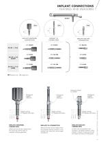
IMPLANT CONNECTIONS FEATURES AND MEASURES IMPLANT HANDWEEL CONNECTION IMPLANT RATCHET CONNECTION Hexagonal head for ratchet Allows removal of the implant from the ampoule and the start of insertion in the surgical site. IMPLANT CA CONNECTION Allows removal of the implant from the ampoule and its insertion in the surgical site using the contra-angle screwdriver. Depth notches for flapless technique 6 mm Depth notches for flapless technique 6 mm Depth notches for flapless technique IMPLANT HANDWEEL CONNECTION Hexagonal implant reference Hexagonal implant reference IMPLANT RATCHET CONNECTION A...
Open the catalog to page 17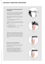
IMPLANTS INSERTION PROCEDURE WITH MANUAL CONTRA-ANGLE IMPLANT CONNECTION Insert the direct manual contra-angle screwdriver into the implant with a slight rotating motion to allow the correct coupling of the two hexagons (implant screwdriver) and remove the implant. (Fig. 5) Begin insertion of the implant in the alveolar surgery (Fig. 6) after having set the following parameters on the surgical unit: 1) Bi-phase procedure (submerged) RPM 15-20 Torque max. 35-40 Ncm 2) Monophasic procedure realized with submerged implants and healing screws, with deferred load RPM 15-20 Torque max. 40-45 Ncm...
Open the catalog to page 18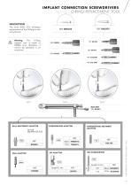
IMPLANT CONNECTION SCREWDRIVERS O-RING REPLACEMENT TOOL The tools (DRO 375) facilitates replacement of the O-Ring on the screwdrivers. Warning The O-Ring support tool is made of PMMA and, therefore, it cannot be sterilised in an autoclave. SCREWDRIVERS ADAPTOR Short Long OVERDENTURE ABUTMENT ADAPTOR Short Long BALL ABUTMENTS ADAPTOR
Open the catalog to page 19
