- Catalogs
- Ortho Solutions
- OxBridge?
OxBridge?

OxBridge?
The document provides comprehensive instructions and specifications for the OxBridge™ Ankle Fusion Nail System, a medical device designed for ankle fusion procedures. It covers the design rationale, key features, instrumentation, indications, surgical techniques, and post-operative care.
Design Rationale
The OxBridge™ Ankle Fusion Nail is engineered to simplify tibiotalocalcaneal arthrodesis, addressing severe pain and disability due to bone loss or deformity. It offers stable fixation with dynamic or static locking options, made from MRI-compatible titanium alloy for enhanced elasticity and strength.
Key Features
- Rotational stability and axial compression via independent cannulated screws.
- Dynamic and static proximal locking screw options.
- Variety of nail diameters and lengths for anatomical variations.
- Low profile cortical screws to reduce soft tissue irritation.
- End caps to prevent screw migration and tissue ingrowth.
Instrumentation System
The system is designed for efficiency, with all instruments in a single tray. Key components include an outrigger jig for screw placement, a reaming rod for reamer positioning, and a primary jig for nail entry alignment.
Indications & Contraindications
Indications include arthritis, failed ankle replacements, and trauma. Contraindications include active infections and inability to adhere to post-operative care.
Preoperative Planning & Surgical Technique
Involves clinical assessment and imaging. The technique includes patient positioning, surgical exposure, and fusion site preparation, emphasizing accurate nail entry and reaming.
Nail Size Selection
Based on preoperative templating and intra-operative assessment, recommending a nail slightly smaller than the reamed diameter to reduce fracture risk.
Assembly and Alignment
Details the process of securing the nail in the alignment jig, ensuring correct orientation and engagement.
Nail Insertion
Describes advancing the nail through the foot using rotational movements and monitoring progress with imaging.
Screw Placement
Outlines the procedures for proximal tibial, LM distal, and PA screw placements, ensuring proper alignment and depth.
Oxbridge™ AFN – MISS-A-NAIL Technique
Describes setting up the jig for miss-a-nail screw insertion and ensuring the compression screw is flush to the calcaneum.
Post-Operative Care
Includes placing patients in a splint, restricting weight bearing, and conducting follow-up X-rays. Advises against smoking and NSAIDs during recovery.
Extraction Procedure
Involves removing the end cap and cortical locking screws, using an extraction bolt and slap hammer to withdraw the nail.
Product Specifications
Lists components of the system, including sizes of screws and end caps, and details the tray layout.
Manufacturing and Legal Information
Ortho Solutions Ltd manufactures the device, with contact information provided for their offices. The device is restricted to sale by or on the order of a physician.
Conclusion
The document serves as a detailed guide for the OxBridge™ Ankle Fusion Nail System, emphasizing adherence to procedures and correct component use for successful outcomes.
Catalog excerpts

OxBridge™ Ankle Fusion Nail Design Rationale & Surgical Technique
Open the catalog to page 1
OxBridge™ Ankle Fusion Nail Clinical Design Team Design Goal - Simplifying the Complex BMBch MA FRCS (Trauma & Ortho) Tibiotalocalcaneal arthrodesis is a successful treatment for patients with severe pain and functional disability. Combined fusion of the ankle and subtalar joints is often used in the complex case, with significant bone loss or deformity. Consultant Orthopaedic Surgeon in Foot & Ankle Surgery at Nuffield Orthopaedic Centre, Oxford. UK Consultant Orthopaedic Surgeon in Foot & Ankle Surgery at Nuffield Orthopaedic Centre, Oxford. UK Consultant Orthopaedic & Trauma Surgeon, Addenbrookes...
Open the catalog to page 2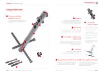
OxBridge™ Ankle Fusion Nail Dynamic or Static Locking Options Choice of dynamic and static proximal locking screw options allow dynamic loading of the nail if required. The nail is made from Titanium alloy (Ti6AI4V), Type II anodised. The material offers improved modulus of elasticity, fatigue strength and biocompatibility compared to stainless steel and is MRI compatible. Nail Sizing Three nail diameters (10mm,11mm & 12mm) each offering two nail lengths (150mm & 180mm) accommodate anatomical variation and reduce inventory requirements. 4 Low Profile Cortical Screws • Ultra low profile heads...
Open the catalog to page 3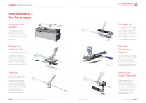
OxBridge™ Ankle Fusion Nail Instrumentation – Key Advantages Instrumentation System Outrigger Jig The outrigger jig has been designed to be simple, accurate and easy to use. The trigger mechanism allows for quick and easy rotation of the radial arm through medial, posterior and lateral positions around the nail axis. The radial arm is made from radiolucent PEEK to facilitate full X-Ray visualisation in multiple planes. The OxBridge instrument set and surgical technique have been designed to be as simple and straightforward as possible. All the instruments are supplied in one tray and laid out...
Open the catalog to page 4
OxBridge™ Ankle Fusion Nail Indications & Contraindications Indications: Relative/Absolute Contraindications Combined arthritis of the ankle and subtalar joints Failed Ankle Replacement Revision of failed ankle and / or subtalar fusion Revision of failed tibiotalocalcaneal (TTC) fusion Correcting neuromuscular imbalance of the hindfoot, where joint fusion is required Talar Avascular Necrosis Charcot neuroarthropathy of the hindfoot Trauma Rheumatoid arthritis Pre-Existing deep active infection Soft tissue defects, unless concomitant procedures planned Patients with psychiatric or neurological...
Open the catalog to page 5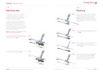
OxBridge™ Ankle Fusion Nail 1/ Nail Entry Site The 8.0mm cannulated starter reamer (from OS333013 disposable pack) is advanced over the 3.9mm guide wire through the sole of the foot, reaming through the subtalar and tibiotalar surfaces, into the tibia (Fig 2a). It is useful to have an assistant hold the foot in the appropriate alignment during the transmedullary reaming, alternatively the foot position can be stabilised with threaded wires. Holding the foot in the correct alignment, the cannulated starter reamer is withdrawn, leaving the guide wire in place (Fig 2b). The exchange tube (from OS333013...
Open the catalog to page 6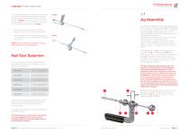
OxBridge™ Ankle Fusion Nail Remove the exchange tube. Sequential reaming is now carried out, using the flexible nitinol reamer shaft and modular heads (contained within the set). The canal is opened up (Fig 2e) in 0.5mm increments until reaming becomes tight, or the canal is reamed to 1mm greater than the diameter of the selected nail (Fig 2f). Make sure the 2.6 x 900mm olive tipped reaming rod (OS201526) is left in the tibia when the reamers are removed. The outrigger is designed for quick and simple assembly. Firstly, locate the Nail Alignment Shaft (B – OS333503) in the main Outrigger Arm...
Open the catalog to page 7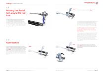
OxBridge™ Ankle Fusion Nail 4/ Rotating the Radial Arm around the Nail Axis To rotate the Main Outrigger Arm about the axis of the nail, and position the outrigger radial arm posteriorly, medially or laterally, depress the trigger (highlighted in blue) until the key disengages from the nail alignment shaft. This will allow the radial arm and the alignment shaft to freely rotate around the longitudinal axis of the nail. There are four key positions located at 90 degree intervals. The nail is advanced, through the sole of the foot, over the olive tipped reaming rod (Fig 5b). Usually the nail can...
Open the catalog to page 8
OxBridge™ Ankle Fusion Nail 6/ Proximal Tibial Screw Placement Drill until you feel drill penetration just through the lateral tibial cortex (Fig 6c). Then stop drilling. If necessary confirm the position of the tip of the drill and then note the desired screw length from the mark on the 4.0mm drill against the drill guide. Use the olive tipped reaming rod to confirm the drill has been correctly targeted through the nail. The wire, when reinserted up the nail, will be stopped by the drill if the drill is through the nail (Fig 6d) Next withdraw the olive tipped reaming rod a further two or three...
Open the catalog to page 9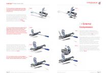
OxBridge™ Ankle Fusion Nail TIP: If the guide wire is passed again from distal to proximal, it will be stopped at an earlier depth, indicating that the second drill has also passed through the nail. The long drill is removed. The drill guide is unscrewed from within the jig guide tube (again ensuring the guide tube remains in contact with the tibial cortex). Couple the pear shaped handle (OS333025) and the self-retaining screwdriver shank (OS333020). Load the tip of the driver with the selected 5mm cortical screw (Fig 6g). Advance the screw through the guide tube (Fig 6h). TIP: You can double...
Open the catalog to page 10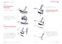
OxBridge™ Ankle Fusion Nail 8/ LM Distal Screw Placement Once compression has been applied, the radial arm is rotated to a lateral orientation (Fig 8). Using image intensification confirms that the distal screw positions will be in bone, distal to the ankle joint. The trocar and drill guide stack are passed through the holes marked L and an AP image is taken. The screws are inserted using the same technique described above for the tibial holes (Fig 8a). Once all screws have been inserted, check radiographs should be taken using the image intensifier, and images stored. If the preoperative planning...
Open the catalog to page 11All Ortho Solutions catalogs and technical brochures
 Foot Osteotomy System
4 Pages
 Memo Staple
2 Pages
 UltOS™ Foot Plating System
36 Pages
 Universal Locking Plate
12 Pages
 Memo? Staple
2 Pages
 Foot Plating System
12 Pages
 Compression Screw System
2 Pages
 Ring Fixator System
8 Pages
 Sterile Plates & Screws
8 Pages
 Toe Grip®
4 Pages
 Twist Off
2 Pages


- Bone plate
- Compression plate
- Metallic compression plate
- Locking compression plate
- Distal compression plate
- Orthopedic surgery instrument kit
- Compression bone screw
- Metallic compression bone screw
- Diamond burr
- Drill bit
- Arthrodesis nail
- Cutting burr
- Lateral compression plate
- Medial compression plate
- Metal burr
- External fixation system
- Metallic intramedullary nail
- Adult external fixation system
- Cannulated compression bone screw
- Arthrodesis plate