Laboratory Vacuum Systems - PBMI (IN592700AV 08/12)

Laboratory Vacuum Systems - PBMI (IN592700AV 08/12)
This document provides detailed instructions for the assembly, installation, operation, and maintenance of the Powerex Laboratory Vacuum System. It emphasizes the importance of safety and understanding the manual to prevent personal injury and equipment damage. A separate safety booklet accompanies this manual.
Control Panel - Display and Input
The system features an HMI panel for operation and monitoring. The main screen displays the pump type and allows access to pump status, alarm status, trends, and service information. The system is controlled by a PLC and meets NFPA 99 requirements for level 1 vacuum. It includes audible and visual alarms, an HOA switch for each pump, and optional email notifications for service alerts.
General Safety Information
Safety information is crucial for preventing equipment problems and ensuring operator safety. The manual includes a table of contents for easy navigation.
Status Screens
The status screens display vacuum levels, system status, alarm status, service info, and trends. Vacuum levels change color based on status: green (normal), orange (low), and red (alarm).
Alarm Screens
Alarm screens show current alarms and service alerts, allowing users to acknowledge and reset alarms. An alarm log records all alarms, warnings, and service alerts with timestamps.
Maintenance Screens
Maintenance screens provide instructions at specific intervals for pump maintenance. The system can be expanded by adjusting the PLC program for additional pumps.
Gateway Start-Up
The 460MX-S027 Gateway connects Modbus RTU Slave devices to a BACnet®/IP client. The setup requires specific tools and network configuration steps, including IP address adjustments.
Gateway Troubleshooting
If the main page does not launch, verify the IP address and network connection. Use command prompt tools to diagnose connectivity issues.
BACnet®/IP Server Settings
Configure the BACnet® server settings by enabling the server, entering device information, and specifying the number of objects to expose.
Alarm Configuration
Enable alarms by setting low and high alarm thresholds. Configure email notifications for alarm alerts.
Email Configuration
Set up email notifications by entering SMTP details and recipient information. Test email settings to ensure accuracy.
System Status
This page displays Modbus points, their values, and alarm statuses. Alarms are highlighted in red.
Locking the System
Lock the system by setting a username and password. If credentials are forgotten, contact Powerex for a reset.
Catalog excerpts
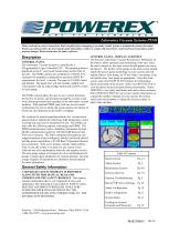
Laboratory Vacuum Systems-PXMI Please read and save these instructions. Read carefully before attempting to assemble, install, operate or maintain the product described. Protect yourself and others by observing all safety information. Failure to comply with instructions could result in personal injury and/or property damage! Retain instructions for future reference. CONTROL PANEL - DISPLAY AND INPUT The Powerex Laboratory Vacuum System has a HMI panel on CONTROL PANEL the front to allow operation and monitoring of the unit. Once The Laboratory Vacuum System is controlled by a the unit is turned on, the main screen should appear (see exam(Programmable Logic Controller) PLC. The operating status is ple below). The picture of the pump on the main screen should displayed on the 6” color touch Screen panel on the front of match the type of pump technology on your system and will the unit. The PXMI controls are contained in a NEMA 4/12 display either a claw pump, an oil-less rotary vane pump, or an enclosure for multiplex configurations and meet NFPA 99 oil-sealed rotary vane pump as appropriate. From the main requirements for level 1 vacuum. The panel is UL508A listed screen, select the PUMP STATUS button for information and labeled. The panel door will also include: audible and about each pump on the system. Select ALARM STATUS to visual alarms with an acknowledge button and an HOA switch view the alarm screen and alarm history information. Select for each pump. TRENDS to view daily load factor and total system run hours. Select SERVICE INFO for our service contact information, to The PXMI controls allow the user to view system functions, expand the number of pumps on your system, the system the factory set points, and navigate through the screens to get model and serial number, to adjust the screen contrast, or more information about the operation of the individual vacuum adjust time and date. modules. With optional PBMI card, staff can receive email notifications for service alerts and system alarms, the details of which are also displayed on the built-in webpage. Dry contacts for remote signaling include: low vacuum and a general fault to indicate the following: high temperature, motor overload trip, and reserve transformer in use. The PXMI controls offer the following options: auto-purge and PBMI. The PBMI communication card is a Building Automation System (BAS) communication gateway with BacNet® protocol and Web server features. The BAS communication gateway can support hundreds of pre-configured, labeled, and listed individual data points and utilizes a 10/100 BaseT Operation Ethernet port connection. Web server features include email notifications in case the system is in alarm for any reason or has achieved one of its maintenance intervals and requires service. The auto-purge option will control all valves and hardware for pumps to purge upon satisfaction of vacuum demand. See auto -purge sequence of operations in Laboratory System manual for more information. A SEPARATE SAFETY BOOKLET IS PROVIDED ALONG WITH THIS MANUAL. READ AND UNDERSTAND THE SAFETY BOOKLET. This manual contains information that is very important to know and understand. This information is provided for SAFETY and to PREVENT EQUIPMENT PROBLEMS. MAKE SURE EVERYONE OPERATING OR SERVICING THE COMPRESSOR READS AND UNDERSTANDS ALL THE INFORMATION PROVIDED. Alarm Screens Maintenance Screens Gateway Start-Up Gateway Troubleshooting BACne®t/IP Server Settings Alarm Configuration Email Configuration System Status Locking the System/ Username and Password General Safety Information Status Screens Powerex - 150 Production Drive - Harrison, Ohio 45030 - USA 1-888-769-7979 - www.powerexinc.com
Open the catalog to page 1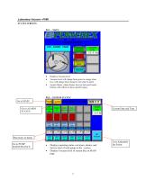
Laboratory Vacuum—PXMI STATUS SCREENS PG1—’MAIN’ Displays Vacuum level Vacuum level will change from green to orange when low; will change from orange to red when in alarm System Status, Alarm Status, Service Info and Trends buttons will redirect to those specific pages Go to MAIN Go to ALARM STATUS Current Date and Time Run hours of pump Go to PUMP MAINTENANCE Displays operating status, run hours, alarms, and Service alert of each pump on the system Displays Vacuum level of system like on MAIN page User Adjustable Set Points
Open the catalog to page 2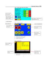
Laboratory Vacuum—PXMI PG3—’USER ADJUSTABLE SET POINTS’ Enter elevation in feet/1,000 Press Default to return to set points to factory settings Press display to adjust Cut-in’s and Differentials only ALARM SCREENS Acknowledge system is in alarm Reset alarm if problem has been corrected Displays alarms and service alerts Acknowledge and reset alarms Displays Vacuum Level Scroll page up or down to see more records Select a specific record Record of all alarms, warnings and service alerts with date and time
Open the catalog to page 3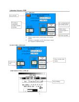
hor service call POWEREX @ SYSTEM MODEL # SYSTEM SERIAL # ABCDEFGHI JKLfMl ADJUST SCREZN SYSTEM MODEL* SYSTEM SERIAL # ADJUST SCREEN SYSTEM MODE TOP PAGE Sinflate Offline*
Open the catalog to page 4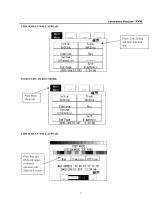
SYSTEM MODE TOP JAGE Simulate Offline
Open the catalog to page 5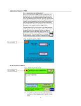
During normal operation the PBMI controller will signal the Lead compressor to run when pressure drops below lead cut-in set point and stop when the pressure reaches the lead cut-out set point. Lead alternation to the next pump, will occur with each lead run signal or every 10-minutes (which ever happens first) If demand cannot be satisfied by the lead pump, the lag pump(s) wil start and stop based upon the lag cut-in and cut-out set-points and lead alternation will occur when the lo west cut-out set-point is satisfied, or10-minutes (which ever happens first). The RPUI (Reserve Pump In Use) alarm,...
Open the catalog to page 6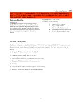
Laboratory Vacuum—PXMI NOTE: PAGES 7-12 ARE INSTRUCTIONS FOR OPTIONAL PBMI WEBSERVER/ BACNET® GATEWAY CARD. THESE INSTRUCTIONS ARE NOT APPLICABLE FOR SYSTEMS WITH HMI ONLY. REQUIRED TOOLS AND DATA You will need the following tools: Gateway Start-Up OVERVIEW The 460MX-S027 Gateway device seamlessly connects Modbus RTU Slave devices to a BACnet®/IP client. By following this guide, you will be able to configure the 460MXS027 Gateway for basic operation. You will set the device’s network settings and parameters to the proper configuration for initial operation and physically place the device in the...
Open the catalog to page 7All Powerex catalogs and technical brochures
 Medical Vacuum Systems
6 Pages
 Powerex Kobelco
4 Pages
 Scroll Enclosure (SE)
4 Pages
 Powerex Overview
6 Pages
 Seismic (OSHPD)
4 Pages
 SR4562 Heat Manager
1 Page
 Rotary Tooth
4 Pages
 Medical Gas Solutions
4 Pages
 IVS/IVD Models
1 Page
 Dewpoint Monitor
2 Pages
 AS/AD Models
1 Page
 Laboratory Air Systems
24 Pages
 Laboratory Vacuum Systems
6 Pages
 Medical Package System
20 Pages
 Instrument Air Systems
2 Pages
 Instrument Air Package System
16 Pages
 Scroll Medical Air Package
12 Pages
 Medical Air Systems Brochure
6 Pages
 Oil-less Vane Vacuum Systems
8 Pages
 Laboratory Vacuum Systems
16 Pages
 Enclosed Oilless Scroll
4 Pages
 Medical Vacuum - Claw
6 Pages
 Medical Air Enclosed Scroll
6 Pages


- Dry air compressor
- Hospital compressor
- Gas outlet
- Gas valve
- Medical device control panel
- Manifold
- Pressure control system
- Medical gas manifold
- Medical gas valve
- Medical monitoring system
- Check valve
- Anesthetic gas alert system
- Medical vacuum system
- DIN outlet
- Flow control panel
- Medical gas supply unit
- Medical gas alert system
- Medical gas sensor