

Scroll Enclosure Air Compressor 30HP to 40HP

Scroll Enclosure Air Compressor 30HP to 40HP
Powerex Scroll Enclosure Air Compressors provide continuous oil-free air using advanced scroll technology. They are quiet, energy-efficient, and require minimal maintenance due to their oil-less rotary design. The scroll compression involves two spirals forming gas pockets that compress air as they move towards the center, eliminating the need for valves.
The compressors range from 30 HP to 40 HP, with operating voltages of 208-230/460/575 Volts at 60 Hz and 380 volts at 50 Hz. They feature a scroll compression cycle, motor overload protection, and pressure settings with cut-in and cut-out points. The units include a UL508A listed control panel and a 3V belt drive.
Operators must read and understand all safety information to prevent equipment problems and personal injury. Key safety measures include wearing protective gear, ensuring proper electrical connections, and maintaining a safe distance from moving parts. The compressor should not be used for breathing air without additional safety equipment.
Installation requires a clean, well-ventilated area free from excessive dust and moisture. Proper electrical connections must be made by a qualified electrician, adhering to local and national codes. The compressor should be securely mounted, and adequate ventilation must be ensured to prevent overheating.
Regular inspection and maintenance are crucial for safe operation. This includes checking for damage, ensuring tightness of fasteners, and draining moisture from tanks to prevent rust and corrosion. Safety valves must be kept free from obstructions and should not be adjusted.
The compressor is not suitable for supplying breathing quality air without proper filtration and alarm systems. Using the compressor for such purposes without these systems voids warranties and releases Powerex from liability.
The product must be grounded to reduce the risk of electrical shock. It requires a 3-phase supply circuit, and specific wire sizes are recommended based on horsepower and voltage.
Ensure piping is aligned without strain, use expansion loops to avoid stress, and anchor supports separately to reduce noise. Flexible hoses should connect the compressor outlet to prevent vibration transfer.
Install remote intake piping at the final site. Intake filters do not prevent liquid water ingestion, which can damage pumps and void warranties.
Do not use PVC for compressed air. All components must withstand generated temperatures and pressures. Safety valves must be installed on every receiver, and check valves should not be placed between the compressor and air receiver.
The compressor features a power control switch and touch screen for operation. Before starting, ensure all connections are secure, and check motor rotation. The system uses multi-stage control to optimize operation based on air consumption.
Follow pre-start-up checks, ensure isolation valves are correctly positioned, and verify display screen functionality. For shut-down, use the OFF button and switch off the breaker if not in use for extended periods.
The compressor employs multi-stage control to manage air ends based on demand, equalizing usage and saving energy. Users can adjust pressure settings to minimize power consumption.
In emergencies, stop the compressor using the OFF button or main disconnect panel.
The compressor is controlled by a PLC with a touch screen interface, allowing parameter adjustments and monitoring of compressor modules.
To start the compressor, ensure the isolation valve is open and monitor the pressure. If the pressure does not rise, the unit may be running backwards, requiring phase adjustment by a qualified electrician. The compressor will automatically stop each pump as needed to maintain pressure between set points. Adjust pressure settings using the HMI screen. Monitor the ALARM screen for high temperature or motor overload conditions. Adjust set points to reduce motor starting frequency if necessary.
The control system divides the pressure range into intervals. Adjust the differential by selecting STANDARD, MIN, or MAX settings to manage motor start frequency. Pressure settings must be whole numbers, and the system will automatically adjust out-of-range inputs.
High temperature or motor overload will trigger alarms, shutting off affected motors. Determine and correct the cause before resetting the system. The PUMP MAINT indicator signals when maintenance is due. Reset counters after maintenance to avoid false alerts.
Regularly inspect and replace components such as intake filters, ventilation screens, and belts according to the maintenance schedule. Lockout/tagout procedures must be followed during maintenance to ensure safety.
Common issues include no display, failure to operate, and alarm conditions. Solutions involve checking power sources, replacing fuses, and inspecting wiring. High temperature alarms may result from poor ventilation or clogged components, requiring cleaning or replacement.
- Motor Overload: Causes include low voltage, motor failure, air end failure, loosened wiring screw, high exhaust pressure, and thermal overload failure. Solutions involve checking electric source capacity, inspecting, repairing, replacing, and tightening components.
- Exhaust Pressure Issues: Causes include air leaks, backward air-end rotation, wrong pressure setting, and clogged intake filter. Solutions involve inspecting, repairing, changing phases, readjusting, and cleaning or replacing filters.
- Safety Valve Activation: Caused by safety valve failure or pressure setting failure. Solutions include replacing the valve and inspecting for control failure.
- Abnormal Sound: Causes include backward air-end rotation, air end failure, belt slippage, motor failure, cooling fan contact, and loosened bolts. Solutions involve changing phases, inspecting, repairing, replacing, checking tension, and tightening bolts.
Specifications for 30HP and 40HP systems include motor size, power, motor load, and panel load. Branch circuit protection involves non-time delay fuses, time delay fuses, and inverse time circuit breakers with specific amperage ratings.
Includes parts such as air ends, motors, pulleys, PLCs, belts, filters, sensors, valves, contactors, transformers, and fuses with specific part numbers for 30HP and 40HP systems.
- General Warranty: Covers defects in material and workmanship for products used in the U.S. and Canada. Claims must be made in writing.
- Standard Warranty: Covers parts and labor for 18 months from shipment or 12 months from startup, or 5,000 hours of use.
- Premium Warranty: Extends coverage to 30 months from shipment or 24 months from startup, or 7,500 hours of use.
- Additional Warranty: Covers parts only for 42 months from shipment or 36 months from startup, or 10,000 hours of use.
- Replacement Parts Warranty: Covers parts only for 12 months from shipment.
- Exceptions: Warranty does not cover improper installation, maintenance, modifications, or operation beyond rated capacities.
Powerex limits liability to the purchase price paid and excludes incidental, consequential, and indirect damages.
Non-warranty claims related to the products must be filed within six months from the invoice date. Powerex is not responsible for delays or failures due to uncontrollable events such as natural disasters or supply issues. Products are inspected before shipment, and any transit-related discrepancies or damages should be claimed directly with the carrier. Returned products require prior written authorization from Powerex.
The limited warranty terms govern all transactions unless otherwise agreed in writing. Conflicting terms on buyer's order forms are not applicable. All orders require acceptance by Powerex.
Catalog excerpts
Scroll Enclosure Air Compressor 30 HP to 40 HP Please read and save these instructions. Read carefully before attempting to assemble, install, operate or maintain the product described. Protect yourself and others by observing all safety information. Failure to comply with instructions could result in personal injury and/or property damage! Retain instructions for future reference. DESCRIPTION GENERAL Powerex Scroll Enclosure Air Compressors are designed to supply continuous oil-free air by using the most advanced scroll technology. These turn-key packages are extremely quiet and offer electronic control that will reduce electrical power consumption. The Powerex Oil-less Rotary Scroll Air Compressor has advanced scroll compressor technology through the development of a completely oil-less unit. The Powerex Scroll Compressor offers a dynamically balanced air end which insures vibration-free operation. The rotary design permits a continuous 100% duty cycle. No oil separation, oil filtration, or inlet valves are required on the Powerex Scroll unit. The compressor is virtually maintenance free. The Powerex Oil-less Rotary Scroll Air Compressor is based on the theory of scroll compression. A scroll is a free standing, intricate spiral bounded on one side by a solid, flat plane or base. A scroll set, the basic compression element of a scroll compressor, is made up of two identical spirals which form right and left hand parts. One of these scroll components is indexed or phased 180° with respect to the other so the scrolls can mesh. Crescent-shaped gas pockets are formed and bounded by the spirals and the base plate of both scrolls. As the moving scroll is orbited around the fixed scroll, the pockets formed by the meshed scrolls follow the spiral toward the center and diminish in size. The moving scroll is prevented from rotating during this process so the 180° phase relationship of the scrolls is maintained. The compressor’s inlet is at the outer boundary of the scrolls. The entering gas is trapped in two completely opposite gas pockets and compressed as the pockets move toward the center. The compressed gas is discharged through the outlet at the center of the fixed scroll so no valves are needed. Parts List Performance Specifications Grease-filled Bearing Operating Voltages Compression Cycle Motor Overload Protection Motor Protector/Circuit Breaker Pressure Settings Cut in: 90 psig Cut out: 116 psig Cut in: 119 psig Cut out: 145 psig (High Pressure Units) Overpressure Protection Safety Valve Factory Set and Sealed See page 2 See Page 6, Chart 3 Control Panel SE Series Enclosed Scroll Air Compressor Tank Sizes Table of Contents Specifications Powerex - 150 Production Drive - Harrison, Ohio 45030 - USA 1-888-769-7979 - www.powerexinc.com
Open the catalog to page 1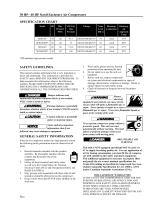
30 HP– 40 HP Scroll Enclosure Air Compressors SPECIFICATION CHART Model Discharge Connection Discharge Air Approach Temp *HP indicates high pressure model. SAFETY GUIDELINES This manual contains information that is very important to know and understand. This information is provided for SAFETY and to PREVENT EQUIPMENT PROBLEMS. To help recognize this information, observe the following symbols. MAKE SURE EVERYONE OPERATING OR SERVICING THE COMPRESSOR READS AND UNDERSTANDS ALL THE INFORMATION PROVIDED. Danger indicates and imminently hazardous situation which, if not avoided, WILL result in death...
Open the catalog to page 2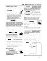
30 HP - 40 HP Scroll Enclosure Air Compressors GENERAL SAFETY CONT. 9. Do not wear loose clothing or jewelry that will get caught in the moving parts of the unit. Surface may be hot even if unit is stopped. 10. Keep fingers away from a running unit; fast moving and hot parts will cause injury and/or burns. 11. If the equipment should start to vibrate abnormally, STOP the unit and check immediately for the cause. Vibration is generally a warning of trouble. 12. To reduce fire hazard, keep unit exterior free of oil, solvent, or excessive grease. An ASME code safety relief valve with a setting no...
Open the catalog to page 3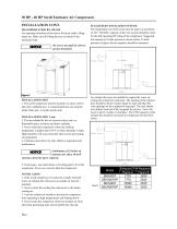
30 HP - 40 HP Scroll Enclosure Air Compressors INSTALLATION CONT. TRANSPORTATION BY CRANE Use openings at bottom of the unit to lift up by cable, lifting straps etc. Make sure all lifting devices are rated for the maximum load. SUGGESTED VENTILATION SYSTEM The temperature rise in the room must be kept to a maximum of 10 F. The BTU capacity of the vent system should be sized for the full operating HP rating of the compressor. Suggested fan capacity at 0 static pressure is shown below. If static pressure is higher, the fan capacity should be increased. Be sure to use pads in order to protect the...
Open the catalog to page 4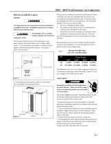
30HP - 40HP Scroll Enclosure Air Compressors INSTALLATION Cont’d WIRING All wiring and electrical connections must be performed by a qualified electrician. Installations must be in accordance with local and national codes. Overheating, short circuiting and fire damage will result from inadequate wiring. The Powerex Scroll Enclosure Air Compressor is completely factory wired and requires only a 3 phase supply circuit. A set of terminals is provided for connection of the supply conductors and ground conductor. See Figure 3 below for more detail. Wiring must be installed in accordance with National...
Open the catalog to page 5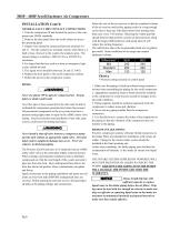
30HP - 40HP Scroll Enclosure Air Compressors INSTALLATION Cont’d GENERAL FAULT DRY CONTACT CONNECTIONS 1. Turn the compressor off and lockout the power to the compressor per OSHA standards. 2. Remove the door panel from the scroll cabinet to access the operating panel. 3. Output wires should be connected between terminals 10 and 11. The dry contacts are normally closed; when there is a fault or loss of power to the system, the contacts open. The contact rating is as follows: 240VAC/2A or 30VDC/2A, maximum. 4. For larger load devices such as a horn or emergency light, a relay should be used. 5....
Open the catalog to page 6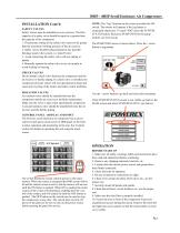
30HP - 40HP Scroll Enclosure Air Compressors INSTALLATION Cont’d SAFETY VALVES Safety Valves must be installed on every receiver. The flow capacity of a safety valve should be equal to or greater than the capacity of the compressor. 1. The pressure setting of the safety valve must not be greater than the maximum working pressure of the air receiver. 2. Safety valves should be placed ahead of any possible blockage point in the system, i.e. shutoff valve. 3. Avoid connecting the safety valve with any tubing or piping. 4. Manually operate the safety valve every six months to avoid sticking or freezing....
Open the catalog to page 7All Powerex catalogs and technical brochures
 Medical Vacuum Systems
6 Pages
 Powerex Kobelco
4 Pages
 Scroll Enclosure (SE)
4 Pages
 Powerex Overview
6 Pages
 Seismic (OSHPD)
4 Pages
 SR4562 Heat Manager
1 Page
 Rotary Tooth
4 Pages
 Medical Gas Solutions
4 Pages
 IVS/IVD Models
1 Page
 Dewpoint Monitor
2 Pages
 AS/AD Models
1 Page
 Laboratory Air Systems
24 Pages
 Laboratory Vacuum Systems
6 Pages
 Medical Package System
20 Pages
 Instrument Air Systems
2 Pages
 Instrument Air Package System
16 Pages
 Scroll Medical Air Package
12 Pages
 Medical Air Systems Brochure
6 Pages
 Oil-less Vane Vacuum Systems
8 Pages
 Laboratory Vacuum Systems
16 Pages
 Enclosed Oilless Scroll
4 Pages
 Medical Vacuum - Claw
6 Pages
 Medical Air Enclosed Scroll
6 Pages


- Dry compressor
- Hospital compressor
- Gas outlet
- Gas valve
- Manifold
- Medical device control panel
- Medical gas manifold
- Pressure control system
- Vacuum system
- Medical gas valve
- Medical monitoring system
- DIN outlet
- Anesthetic gas alert system
- Medical vacuum system
- Flow control panel
- Medical gas supply unit
- Medical gas alert system
- Automatic manifold