
- Catalogs
- Preci-dip SA
- FULL VERSION Edit. No. 14.4

FULL VERSION Edit. No. 14.4
FULL VERSION Edit. No. 14.4
- Insulator: Black glass filled polyester PCT-GF30-FR with UL 94V-O flammability rating.
- Piston and Barrel: Made of Brass CuZn36Pb3 (C36000).
- Spring: Stainless steel X12 CrNi177, DIN 17224.
- Max Stroke: Varies by model, with a maximum of 1.5 mm.
- Forces: Initial force ranges from 0.2 N to 0.25 N, with higher forces at half stroke.
- Mechanical Life: Ranges from 50,000 to 100,000 cycles.
- Operating Current: Maximum of 3.5 A.
- Contact Resistance: Ranges from 10 mΩ to 15 mΩ.
- Coplanarity: SMD terminations have a maximum of 0.1 mm coplanarity.
- Operating Temperature Range: -55 to +125 °C.
- Climatic Category: 55/125/21.
- Operating Humidity Range: Annual mean 75%.
- Max Working Voltage: 100 VRMS/150 VDC for 2.54 mm grid.
- Mechanical and electrical tests include dry heat, damp heat, cold steady state, thermal shock, vibrations, and shock resistance.
- Press-in force: 90 N max.
- Push-out force: 30 N min.
- 2 mm grid: Finished hole Ø: 0.7 + 0.09/-0.06 mm.
- 2.54 mm grid: Finished hole Ø: 1 + 0.09/-0.06 mm.
- Plating options include tin, copper, and gold over nickel.
1. Insulator Material: Black glass filled polyester or polymer (PCT-GF30-FR or LCP-GF30-FR) with UL 94V-O flammability rating.
2. Sleeve Material: Brass CuZn36Pb3 (C36000) or Bronze CuSn4Pb4Zn4 (C54400).
3. Contact Clip: Beryllium copper (C17200) with 4 or 6 finger configurations.
4. Mating Pin Diameter: Ranges from 0.40 to 0.66 mm.
5. Insertion and Withdrawal Forces: Typically 0.7 N insertion and 0.4 N withdrawal.
6. Mechanical Life: Minimum 500 cycles.
7. Rated Current: 1 A or 3 A depending on the connector type.
8. Contact Resistance: Maximum 10 mΩ.
9. Dielectric Strength: Minimum 1,000 VRMS.
Connector Types and Availability:
- Socket Connectors: Available in single or double row configurations with solder tail, right angle, surface mount, or press-fit options. Contact availability ranges from 2 to 100 depending on the model.
- Pin Connectors: Single row with solder tail, available from 2 to 38 contacts.
Ordering Information:
- Connectors are ROHS compliant with various plating options such as Tin Flash gold or 0.75 μm gold.
- Part numbers are customizable based on the number of poles required.
Additional Notes:
- For connectors with more than 12 contacts, coplanarity issues need specific addressing.
- Technical specifications are subject to change due to technical progress.
- For detailed availability and packaging information, consult the website www.precidip.com.
- Insulator Material: Black glass filled polymer LCP-GF30-FR or polyester PCT-GF30-FR.
- Flammability: UL 94V-O.
- Contact Material: Brass CuZn36Pb3 (C36000) or Beryllium copper (C17200) for contact clips.
- Connecting Pin Diameter: Ø 0.47 mm or 0.5 mm for square pins.
- Mechanical Life: Minimum 500 cycles for most connectors, 100 cycles for square pin headers.
- Rated Current: 3 A for most connectors, 1 A for square pin headers.
- Dielectric Strength: Minimum 1,000 VRMS for most connectors, 500 VRMS for square pin headers.
- Press-fit socket connectors are available with 22, 26, and 44 contacts.
- Straight pin connectors are available from 2 to 100 contacts depending on the configuration.
- Right angle pin connectors are available from 2 to 100 contacts.
- SMD pin connectors are available from 3 to 100 contacts.
- Socket connectors are available from 2 to 72 contacts.
- Insulator: Black glass filled polyester PCT-GF30-FR, UL 94V-O flammability rating.
- Sleeve Material: Brass CuZn36Pb3 (C36000) or Bronze CuSn4Pb4Zn4 (C54400) depending on the type.
- Contact Clip: Beryllium copper (C17200) with a 4-finger design.
- Mating Pin Diameter: Ranges from 0.36 mm to 0.56 mm.
- Insertion/Withdrawal Forces: 2 N typical insertion, 1 N typical withdrawal.
- Mechanical Life: Minimum 500 cycles.
- Rated Current: 3 A.
- Contact Resistance: Maximum 10 mΩ.
- Dielectric Strength: Minimum 1,000 VRMS.
- Straight Socket Connectors: Available in single, double, and triple rows with varying contact numbers.
- Interconnect Socket Strips: Offered in single and double rows with solder tail configurations.
- SMD Socket Connectors: Available in low profile, perpendicular, and parallel mounts with self-levelling floating contacts.
- Press-Fit Socket Connectors: Designed for solderless mounting in PCB plated through holes, available for different PCB thicknesses.
- Wire-Wrap Socket Connectors: Feature wire-wrap terminations for secure connections.
- Insulator: Black glass filled polyester PCT-GF30-FR, UL 94V-O flammability rating.
- Sleeve: Brass CuZn36Pb3 (C36000).
- Contact Clip: Beryllium copper (C17200), available in 4, 3, and 6 finger configurations.
- Mating Pin Diameter: Ranges from 0.40 to 0.90 mm depending on the connector type.
- Forces: Typical insertion force is 1.2 N, and withdrawal force is 0.6 N.
- Mechanical Life: Minimum of 500 cycles.
- Rated Current: 3 A.
- Contact Resistance: Maximum of 10 mΩ.
- Dielectric Strength: Minimum of 1,000 VRMS.
- Wire-wrap socket connectors are available in heights ranging from 2.95 mm to 11 mm.
- Contact availability varies from 2 to 100 contacts, depending on the connector type and configuration.
- Standard plating options include Tin Flash gold and Tin 0.75 μm gold, with other plating options available upon request.
- Connectors are identified by a specific part number format, where 'NN' or 'NNN' is replaced by the number of poles required.
- Examples of part numbers and their configurations are provided for clarity.
- All parts are RoHS compliant.
- Due to technical progress, specifications are subject to change without prior notice.
The document provides detailed specifications for socket connectors with a 2.54 mm pitch. The insulator is made of black glass-filled polyester (PCT-GF30-FR) with a flammability rating of UL 94V-O. The sleeve is composed of Brass CuZn36Pb3 (C36000), and the contact clip is made of Beryllium copper (C17200). Mating pins range from Ø 0.70 to 0.90 mm, with a typical insertion force of 1.2 N and a withdrawal force of 0.6 N. The connectors have a mechanical life of at least 500 cycles, a rated current of 3 A, and a maximum contact resistance of 10 mΩ. The dielectric strength is a minimum of 1,000 VRMS.
The document lists various socket connector configurations, including single and double row, solder tail, right angle, and surface mount options. Availability ranges from 2 to 100 contacts, depending on the model. Standard contact numbers are specified for each type, such as 40 for certain double row connectors and 50 for single row configurations.
The connectors are ROHS compliant, with plating options including Tin Flash gold and Tin 0.75 μm gold. The document provides a coding system for ordering, where 'NNN' is replaced with the desired number of poles. Specific examples are given for different configurations.
The document emphasizes that due to technical progress, all information is subject to change without prior notice. It also advises consulting the company's website for details on packaging options, including tape and reel sizes and the number of components per reel.
- Connecting Pin Diameter: 0.76 mm
- Mechanical Life: Minimum 500 cycles
- Rated Current: 3 A
- Dielectric Strength: Minimum 1,000 VRMS
- Insulator: Black glass filled polyester PCT-GF30-FR
- Flammability: UL 94V-O
- Contact Material: Brass CuZn36Pb3 (C36000)
- Pin Connectors: Available in single, double, and triple row configurations with solder tail or surface mount options.
- Shrouded Pin Connectors: Available in single, double, and triple row configurations with solder tail or surface mount options.
- Right Angle Pin Connectors: Available in single and double row configurations with solder tail options.
- Press-fit Pin Connectors: Available in single and double row configurations for PCB thickness 1.5 to 2.5 mm.
- Plating Options: 0.25 μm gold, Tin, or Tin with 0.75 μm gold.
- Number of Poles: Replace 'NNN' with the desired number of poles in the product code.
- Availability: From 2 to 96 contacts depending on the product type and configuration.
- All parts are RoHS compliant.
- Other plating options are available upon request.
- For connectors with more than 9 contacts, coplanarity issues need to be addressed specifically.
- Technical specifications are subject to change due to technical progress.
The document provides detailed specifications for Dual-In-Line (DIL) sockets, including various configurations such as open frame, solder tail, and surface mount options. The insulator is made from black glass-filled polyester (PCT-GF30-FR) with a flammability rating of UL 94V-O. The sleeve is composed of Brass CuZn36Pb3 (C36000), and the contact clip is made from Beryllium copper (C17200). The sockets accept pin diameters ranging from 0.40 to 0.56 mm, with typical insertion and withdrawal forces of 2 N and 1 N, respectively. The mechanical life is rated at a minimum of 100 cycles, with a rated current of 1 A and a maximum contact resistance of 10 mΩ. The dielectric strength is at least 1,000 VRMS.
Ordering Information:
The document includes comprehensive ordering information for various DIL socket configurations, specifying the number of poles, dimensions, and corresponding order codes. It also details options for insulators without center bars, increased solder tail lengths, and sockets with soft brass pins. The document emphasizes that all parts are RoHS compliant and offers different plating options, including tin flash gold and tin with 0.75 μm gold.
Product Variants:
The document outlines several product variants, including automatic insertion sockets, capacitor sockets with ceramic multilayer decoupling capacitors, and ultralow profile sockets. Each variant is designed for specific applications, such as reflow soldering with gull wing terminations for surface mount sockets.
Additional Notes:
The document notes that due to technical progress, all information is subject to change without prior notice. It also provides contact information for Preci-Dip, the manufacturer, for further inquiries and consultations regarding specific requirements or customizations.
1. **Insulator Material**: Black glass filled polyester PA-GF30-FR with UL 94V-O flammability rating.
2. **Sleeve Material**: Brass CuZn36Pb3 (C36000).
3. **Contact Clip**: Beryllium copper (C17200) with a 4-finger design.
4. **Accepted Pin Diameter**: 0.40 to 0.56 mm.
5. **Forces**: Typical insertion force is 2 N, and withdrawal force is 1 N using a polished steel gauge of Ø 0.43 mm.
6. **Mechanical Life**: Minimum of 100 cycles.
7. **Rated Current**: 1 A.
8. **Contact Resistance**: Maximum of 10 mΩ.
9. **Dielectric Strength**: Minimum of 1,000 VRMS.
1. **ROHS Compliant Parts**: Available with different plating options:
- Tin Flash gold (Code 87)
- Tin 0.75 μm gold (Code 83)
2. **Part Numbering**: Replace XXX in the part number with the specific code for the required contact length.
3. **Available Options**: Various configurations for different applications, including ultralow sockets and right-angle versions.
1. **Dual-In-Line Sockets**: Available in open frame, solder tail, and press-fit versions.
2. **Shrinkdip Sockets**: High-density sockets for devices with 0.07” lead spacing.
3. **Pin Carrier Assemblies**: Low profile and ultra-thin options available.
4. **Right Angle Versions**: Designed for perpendicular mounting of components like displays.
1. **Number of Poles**: Ranges from 4 to 64 poles.
2. **Dimensions**: Specific dimensions (A, B, C) provided for each configuration.
3. **Figures**: Reference figures provided for visual guidance on page 128.
1. **Customization**: Other plating and contact lengths available upon request.
2. **Technical Progress**: Information is subject to change without prior notice due to technical advancements.
General Specifications:
- Operating Temperature Range: -55 to +125 °C
- Climatic Category: 55/125/21
- Operating Humidity Range: Annual mean 75%
- Max. Working Voltage: 100 VRMS/150 VDC (2.54 mm grid)
- Insulation Resistance: Min. 10,000 MΩ at 500 VAC
- Capacitance: Max. 1 pF (PLCC max. 2 pF)
- Self Inductance: Max. 2 nH
Mechanical Characteristics:
- Clip Retention: Min. 40 N
- Contact Retention: Min. 3.3 N
- Mechanical Life: Min. 100 cycles
Electrical Characteristics:
- Rated Current: 1 A
- Contact Resistance: Max. 10 mΩ
- Dielectric Strength: Min. 1,000 VRMS
Environmental Tests:
- Dry Heat: 125 °C, 16 h
- Damp Heat: 25/55 °C, 90-100% RH, 1 cycle of 24 h
- Cold Steady State: -55 °C, 2 h
- Thermal Shock: -55/125 °C, 5 cycles 30 min.
- Sinusoidal Vibrations: 10 to 500 Hz, 10 g
- Shock: 50 g, 11 ms
- Solderability: 245 °C, 5 s
- Resistance to Soldering Heat: 260 °C, 20 s
- Moisture Sensitivity: Level 1
Socket Types and Specifications:
- Crystal, Relay, and Display Sockets: Insulator made of black glass-filled polyester, UL 94V-O flammability, brass sleeve, beryllium copper contact clip.
- PGA/BGA/PLCC Sockets: Available in solder tail, surface mount, and solderless compliant press-fit versions. Various grid sizes and configurations.
Ordering Information:
- ROHS Compliant Parts
- Plating Options: Tin, Flash Gold, 0.75 μm Gold
- Custom configurations available upon request.
Contact Information:
- Website: www.precidip.com
- Phone: +41 32 421 04 00
- Email: [email protected]
Note: All information is subject to change due to technical progress.
- Insulator Material: Glass-epoxy laminate FR4 and glass-filled thermoplastic PPS-GF30-FR.
- Flammability: UL 94V-O.
- Contact Materials: Brass CuZn36Pb3 (C36000) and Beryllium copper (C17200).
- Accepted Pin Diameter: Varies by socket type, ranging from 0.20 mm to 0.46 mm.
- Mechanical Life: Minimum 100 cycles for most sockets.
- Rated Current: 1 A.
- Contact Resistance: Maximum 10 mΩ.
- Dielectric Strength: Minimum 500 VRMS.
- Dimensions for sockets and adapters are calculated using specific formulas based on the number of contacts in one line.
- Ordering information requires specifying the number of poles, body size, and layout numbers.
- All parts are RoHS compliant.
- Plating options include flash gold, tin, and 0.25 μm gold, with other options available upon request.
- Consult the catalog for specific part numbers and configurations.
- For custom grid designs, contact PRECI-DIP directly.
- Various grid sizes and configurations are listed, such as 1.27 mm and 1 mm grids for PGA and BGA sockets.
- Specific part numbers are provided for different socket types and configurations.
Specifications:
The document lists socket and pin contacts qualified under various military specifications such as MIL-DTL-38999, MIL-DTL-24308, MIL-DTL-55302, MIL-DTL-83733, MIL-DTL-26482, and MIL-DTL-26500. Each specification includes details on connector types, part numbers, and sizes.
Socket Contacts:
Socket contacts are categorized by connector type and military part number, with specific Preci-Dip part numbers and sizes provided. The document distinguishes between reversed and Eagle Grip clips.
Pin Contacts:
Pin contacts are similarly categorized, with details on overall and localized finishes, Preci-Dip part numbers, and sizes.
Contact Data:
The document provides detailed specifications for various clip codes, including the number of fingers, mating pin diameter range, compliancy, minimum mating pin length, and current rating. Each clip code is associated with specific mechanical properties such as initial insertion force, insertion force for the second cycle, and withdrawal force.
Application Fields:
The document outlines application fields for telecommunications, data processing and acquisition, and transportation. Examples include connectors for mobile radios, SIM cards, mobile phone batteries, data acquisition terminals, LED display sockets, car dashboards, and more.
Key Features:
- Precision machined bodies with custom design options.
- Clips are press-fit into contact bodies.
- Shoulders are preferred to assist assembly.
Note:
All information is subject to change due to technical progress.
- Aircraft, Aerospace, and Military: This section lists connectors used in avionics equipment, military radios, radar equipment, and electronic defense systems. Key features include high-stiffness connectors and sealed connectors with high contact pressure.
- Automation and Industrial Equipment: Connectors for industrial sensors, control systems, and measurement systems are highlighted. Examples include test jacks, SMD connectors, and spring-loaded connectors for programming modules.
- Testing and Measuring: This section covers connectors for weighing systems, liquid analysis, and disk drive testing. Notable types include data interface connectors and shielded contact connectors.
- Medical: Connectors for medical equipment such as breathing assistance devices, blood pressure monitors, and patient monitoring systems are detailed. Features include spring-loaded connectors and overmoulded miniature connectors with IP67 protection.
- Professional and Consumer Electronics: The document lists connectors for devices like ink-jet printers, cameras, and media players. It includes miniature connectors and spring-loaded connectors for various applications.
- Sales Offices and Distributors: Contact information for sales offices in Switzerland and representative offices in Shanghai is provided. A detailed list of distributors across Europe, Asia, and Oceania is included, with links to their websites.
Catalog excerpts
swiss world connects
Open the catalog to page 1
'ffffffffffffffffffffffffffff rrrrrrrrrrrrrrrrrrrrrrrrrrrri 'ffffffffffffffffffffffffffff p H'f ffffffffffff r > r r r r if r r > p r r r r r 'FFFFFFFFFFFFFFFFFFFFFFFFFFFF PPPPPPPPPPPPPPPPPPPPPPPPPPPPf ■lip P PI P (P P Flip r PI P (P P Flip V PI P (P PI Pup P PI P (P PI PI 'FFFFFFFFFFFFFFFFFFFFFFFFFFFF PPPPPPPPPPPPPPPPPPPPPPPPPPPPf 'FFFFFFFFFFFFFFFFFFFFFFFFFFFF P PI P ff P F IP P PI P (f P F IP P P P P P F IF P P P (P P F IF f
Open the catalog to page 2
PRECI-DIP SWISS QUALITY CONNECTION TECHNOLOGY INTERCONNECT COMPONENTS FROM STANDARD PRODUCTS TO CUSTOM DESIGN
Open the catalog to page 3
FIND A WORLD OF SWISS QUALITY
Open the catalog to page 4
FULL CONTROL OF THE ENTIRE MANUFACTURING PROCESS. FROM RAW MATERIAL TO FINISHED PRODUCT, FROM PRODUCT DEVELOPMENT TO SALES. HOME TO SUCH UNIQUE QUALITY IS DELEMONT, SWITZERLAND. SINCE 1976. Excellence and Substained Growth – the Reason why PRECI-DIP received the Entrepreneur of the Year Award for Western Switzerland
Open the catalog to page 6
PRECI-DIP packs unequaled expertise into cutting-edge interconnect components. Advanced designs, top materials, incomparable Swiss precision. Developed by men and women driven by passion and know-how. Key data for one of the world’s leading producers of screw-machined contacts: 25,000 m2, more than 20,000 different products, R & D supported by state-of-the-art CAD systems and 3D projections. Compliance with the Standards ISO 9001, EN 9100, ISO 14001, ISO/TS 16949 and MIL Standard 790 verified in our own test laboratory. ISO 14001 Environmental Management Systems. Ahead of its time, PRECI-DIP exceeds...
Open the catalog to page 7
SCREW- MACHINING 300 automatic high-speed turning machines for cylindrical parts Up to 150 million pieces/week capacity Material: brass or bronze wire in drum or bar
Open the catalog to page 8
CLIP STAMPING • 10 high-speed stamping presses • 130 million clips/week capacity • BeCu material, heat treated and deburred • More than 40 multi-finger clip references
Open the catalog to page 9
CONTACTSASSEMBLY • 150 contact assembly machines for the insertion of the clip in the contact body • 150 million contacts per week assembly capacity Final assembly of the contact in the insulator 150 assembly machines and equipment Assembly PCB connectors, IC and PGA sockets Capacity 80 million assembled contacts per week
Open the catalog to page 10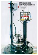
Over 10 million contacts per week assembly capacity Multi-station rotary table: - Components loading - Crimping press - In-line functionality checks
Open the catalog to page 11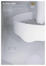
PLATING LINES • 6 fully automated plating lines of the vibratory basket type • 180 million parts / week capacity • Layer deposition: electro nickel, chemical nickel, tin lead, gold, lead-free tin • Chemical lab for plating bathes and waste water treatment analysis and maintenance • Waste water treatment installation with ultra filtrati
Open the catalog to page 12
SPRING COILING • Ultramodern miniature spring coiling machines • Material: music wire or stainless steel • In-built, closed loop measuring system with self-adjustment of spring len
Open the catalog to page 13
Over 2 million parts per week Epoxy plate machining for prototypes and small series RAW MATERIAL STOCK • Brass, bronzA and beryllium copper • Injection moulding plastics • 36 tons raw material consumption per week OPERATIONS • 85 machines to complement machining of elaborated turned parts • Typical operations: bleeding hole, solder cup, press-fit, slanted face, polarizing flat, wire wrap • Multi-station rotary table machines
Open the catalog to page 14
COLOR CODING OF CONTACTS • 8 color coding machines • BIN code or similar identification rings • Deposition of thermo-sensitive paint ink MECHANICAL WORKSHOP • Development and realization of automatic assembling equipment • Construction of mould tools • Maintenance team for productio
Open the catalog to page 15
INSPECTION AND TEST LAB • Laboratory for dimensional, mechanical, electrical and environmental testing • First article inspection and new product qualification SALES AND MARKETING DEPARTMENT • Highly experienced sales force (Key Account Managers – Sales Assistants) • Languages spoken: French, English, German, Spanish, Italian, Japanese, Finnish, Chines
Open the catalog to page 16
PROFIT FROM OUR WORLDWIDE RECOGNITION ADVANTAGE CLIENT Awards from prestigious institutions and customers. Major certifications. Worldwide recognition. For ongoing innovation, perfect teamwork, environmental responsibility as well as entrepreneurial excellence and sustained growth. In short, for swiss quality. Excellence and sustained growth – the reason why PRECI-DIP received the Entrepreneur of the Year Award for Western Switzerland
Open the catalog to page 17
DEMAND THE BEST SOLUTIONS FOR YOUR IDEAS OUR CUSTOM DESIGN A competitive edge, the ability to innovate, and high productivity are some of the core values at PRECI-DIP. When it comes to Custom Design, there’s an additional value: Teamwork. Time and again, turning customer ideas and imagination into reality is a very special challenge. This is one of PRECI-DIP’s core strengths. Everything under one roof: the incomparable advantage of PRECI-DIP becomes even more obvious when it comes to Custom Design. Ready access to material resources is as critical as the expertise of our engineers and the art...
Open the catalog to page 18
CHOOSE THE BEST CONNECTION More than 100 Distributors around the world distribute PRECI-DIP products across the five continents 4 x AUSTRIA 4 x BELGIUM 2 x BULGARIA 2 x BYELORUSSIA 1 x CROATIA 4 x CZECH REPUBLIC 4x DENMARK 4 x ESTONIA 4 x FINLAND 6xFRANCE 5xGERMANY 2xGREECE 4 x HUNGARY 5 x UNITED KINGDOM 2 x UKRAINE
Open the catalog to page 20
• COMPLETE RANGE OF HIGHLY RELIABLE INTERCONNECT COMPONENTS • DIVERSE FIELDS OF APPLICATION • IN-HOUSE MANUFACTURING - FROM RAW MATERIAL TO FINISHED PRODUCT • EFFECTIVE MANAGEMENT SYSTEM • HIGHLY SKILLED AND MOTIVATED WORKFORCE • STRONG CUSTOMER SUPPORT • CUSTOM DESIGN • COMPETITIVE PRICING, FLEXIBILITY AND SWISS QUALITY • WORLDWIDE PRESENCE • PRESTIGIOUS CLIENT BASE
Open the catalog to page 21
• SPRING-LOADED CONNECTORS • SCREW-MACHINED CONTACTS • CUSTOM DESIGN CONNECTORS
Open the catalog to page 23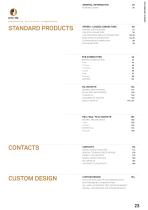
GENERAL INFORMATION STANDARD PRODUCTS SPRING - LOADED CONNECTORS GENERAL SPECIFICATIONS FINE PITCH CONNECTORS LOW RESISTANCE MODULAR CONNECTORS BASIC MODULAR CONNECTORS FLOATING MOUNT CONNECTORS SOCKET CONTACT SELECTOR 177 GENERAL TECHNICAL SPECIFICATIONS 178 DATA SHEET CLIP CONTACTS 185 CUSTOM DESIGN APPLICATION FIELDS FOR TELECOMMUNICATION DATA PROCESSING, TRANSPORTATION MIL / AERO, AUTOMATION, TEST AND MEASUREMENT MEDICAL, PROFESSIONAL AND CONSUMER GOODS
Open the catalog to page 25All Preci-dip SA catalogs and technical brochures
 SPRING-LOADED CONNECTORS
14 Pages
 CLIP TECHNOLOGY
1 Page
 OPEN BOTTOM CONTACTS
1 Page
 STANDALONE BENT CONTACT
1 Page
 LOW PROFILE SPRING CONTACTS
2 Pages
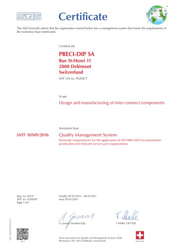 Certificate
1 Page
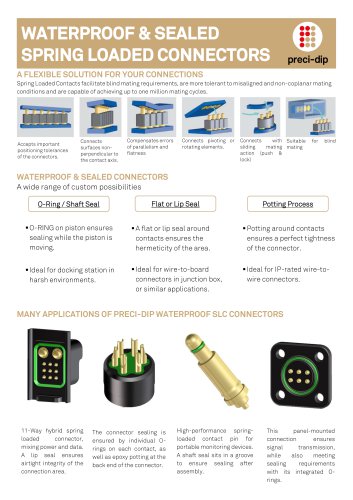
Archived catalogs
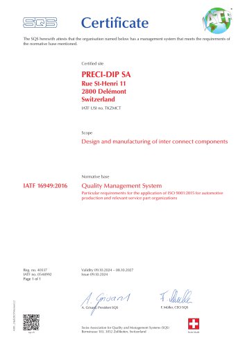 Certificate
1 Page
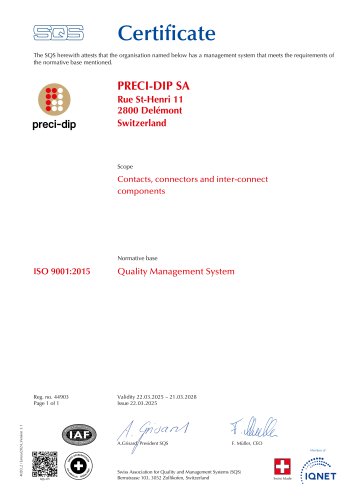 Certificate
1 Page