
- Catalogs
- Reanimed Teknik Tibbi Sistemler Ltd Sti
- General Catalogue


General Catalogue

1 / 125 PagesView full catalog
General Catalogue
Product catalog summary
Technical Diagram Overview
The document appears to be a technical schematic or layout related to instrumentation and electrical connections within a building or facility.
Main Components Identified:
- Manometer & Vacuummeter: Instruments likely used for measuring pressure and vacuum levels.
- RJ45 Data Socket: Network connection point for data communication.
- Grounded & UPS Electric Socket: Electrical outlet with grounding and uninterruptible power supply features, ensuring stable and safe power delivery.
- Equipotential Earth Node: A grounding point designed to maintain equal electrical potential, enhancing safety and reducing electrical noise.
- Structural Elements: References to roof, ceiling roof, and floor indicate the physical placement or mounting locations of the components.
Key Insights:
- The diagram emphasizes proper grounding and electrical safety through the inclusion of grounded sockets and equipotential earth nodes.
- Data connectivity is facilitated via RJ45 sockets, suggesting integration with networked systems.
- The presence of measurement instruments (manometer and vacuummeter) indicates monitoring of environmental or process parameters.
- Structural references imply consideration of installation environment and possibly cable routing or equipment placement.
Recommendations and Best Practices:
- Ensure all electrical sockets are properly grounded and connected to UPS to maintain power integrity.
- Maintain equipotential bonding to prevent electrical hazards and ensure system reliability.
- Position measurement instruments in accessible locations for accurate readings and maintenance.
- Plan cable management considering the building structure (roof, ceiling, floor) to avoid interference and facilitate maintenance.
See more
Catalog excerpts
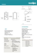
CEILING ROOF MANOMETER& VACUUMMETER GROUNDED&UPS ELECTRIC SOCKET EQUIPOTENTIAL ERATH NODE
Open the catalog to page 55All Reanimed Teknik Tibbi Sistemler Ltd Sti catalogs and technical brochures
 SOFT BED HEAD UNIT
8 Pages
Related Searches
- Container
- Bed head unit
- Medical pendant
- Ceiling-mounted medical pendant
- Medical gas pressure reducer
- Medical gas flow meter
- Wall-mounted bed head unit
- Gas outlet
- Intensive care medical pendant
- Hospital flow meter
- Horizontal bed head unit
- Bed head unit with light
- Medical pendant with shelves
- Medical pressure regulator
- O2 flow meter
- Gas sensor
- Transparent tubing
- Single-arm medical pendant
- Articulated medical pendant
- Adjustable-flow pressure regulator
*Prices are pre-tax. They exclude delivery charges and customs duties and do not include additional charges for installation or activation options. Prices are indicative only and may vary by country, with changes to the cost of raw materials and exchange rates.
About MedicalExpo
MedicalExpo is a marketplace that offers B2B players a complete experience, from product sourcing to purchase. MedicalExpo is an entity of VirtualExpo Group.
Are you a buyer?
Are you a supplier?