- Catalogs
- Shenzhen Witleaf Medical Electronics
- M701 EEG module
- Company
- Products
- Catalogs
- News & Trends
- Exhibitions
M701 EEG module
1 /5Pages

M701 EEG module
1 /5Pages
Catalog excerpts
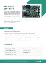
EEG module M701/M701C Use and stick on the forehead surface of the electrode collection of the brain cortex potential difference, and the subsequent voltage amplification, filtering, digital, feature identification, and algorithm processing, so as to obtain EEG signal, and calculate EEG power, brain wave frequency band ratio and other parameters, then through the application of waveform, parameters, for brain disease and action consciousness evaluation and research, is one of the key technology of high-end monitoring application. Features > Measure the two EEG waveforms in real time. > Real-time transmission of the power spectrum parameters calculated based on EEG signals. > Calculate the signal quality index and evaluate the signal quality according to the EEG signals in real time. > Average time setting function of calculation parameters to obtain different response times of calculation parameters. > 12V DC power supply, the system with DC / DC power supply, meet the safety isolation requirements. Performance Input signal range:+/- 1000uV DC current offset voltage > +/- 400 mV Co-mode inhibition ratio > 105 dB For more information, please contact us: sales@szwitleaf.
Open the catalog to page 1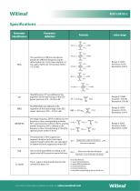
Specifications Parameter identification Parameter definition Total EEG power TP was defined as the logarithm of the total energy of the EEG power spectrum of 0 – 30 Hz in dB The EMG EMG was defined as the logarithm of the total energy of the EEG power spectrum of 30 – 47 Hz in dB value range The waveforms of EEG can be decomposed into different frequency bands: delta rhythm (0.5-3 Hz), theta rhythm (4-7 Hz), alpha rhythm (8-12 Hz), beta rhythm (13-30 Hz) Range: 0-100% Accuracy: 0.01% Resolution: 0.01% Range: 0-100db Accuracy : 0.01db Resolution: 0.01db Range: 0-100% Accuracy: 0.01% Resolution:...
Open the catalog to page 2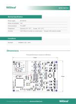
Electical Specification Power supply 0-85% Relative humidity (no condensation) Compliance Standard Dimensions The board dimensions are given in millimeters. For more information, please contact us: sales@szwitle
Open the catalog to page 3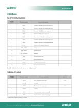
Interfaces The J2 FPC Interface Definition The pin number function symbol function declaration Channel 1 with the EEG forward input end Channel 1 with the EEG negative input end Channel 2: The EEG forward input end Channel 2 EEG negative input end Channel 3 with the EEG forward input end Channel 3 with the EEG negative input end Channel 4: The EEG is the forward input end Channel 4 EEG negative input end Shield interface Shield interface grounding electrode grounding electrode Note: J2 refers to the socket connected to the sensor. Definition of J1 socket The pin number Function symbol The 12V...
Open the catalog to page 4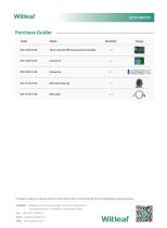
Purchase Guider Code String line * The data is subject to change without notice. Please refer to the manual for the contraindications and precautions Address:Building A-1201, Senyang High-tech Park, Yutang Street, Guangming District, Shenzhen, Guangdong, China Tel:+86 0755-21384132 Email:[email protected] Web:www.szwitlea
Open the catalog to page 5All Shenzhen Witleaf Medical Electronics catalogs and technical brochures
 W12/W15 Series
6 Pages
 VS1000 patient monitor
5 Pages
 XH-80 Patient Monitor
6 Pages
 E10E12E15
5 Pages
 L10L12L15
5 Pages
 XH-60 Vital Signs Monitor
4 Pages
 Carbon dioxide monitor
4 Pages
 WITLEAF OEM Solutions Catalog
16 Pages
 Multi-parameter Module M001
2 Pages
 Multi-parameter Module M011
2 Pages
 Multi-parameter Module M103
2 Pages
 12 Leads ECG Module M108
2 Pages
 3/5 Leads ECG Module M101
2 Pages
 CapnoSET CO2 Sensor
2 Pages
 Multi Parameter Patient Monitor
17 Pages


- Blood pressure monitor
- Automatic blood pressure monitor
- Patient monitor
- SpO2 monitor
- Medical sensor
- Medical pulse oximeter
- Blood pressure patient monitor
- ECG patient monitor
- SpO2 patient monitor
- Multi-parameter monitor
- Fingertip pulse oximeter
- Monitoring sensor
- Intensive care patient monitor
- Portable patient monitor
- NIBP patient monitor
- Blood pressure monitor with adult cuff
- TEMP patient monitor
- Compact patient monitor
- Multi-parameter O2 monitor
- Pulse oximetry multi-parameter monitor