- Catalogs
- Skeletal Dynamics
- ALIGN ® Surgical Technique Guide
ALIGN ® Surgical Technique Guide

ALIGN ® Surgical Technique Guide
The document is a surgical technique guide for the ALIGN Radial Head System, authored by Jorge L. Orbay, M.D. It provides detailed instructions for replacing the radial head to restore motion and stability using the ALIGN system.
Distal Ulna and Elbow Landmarks
Key landmarks for identifying the axis of forearm rotation include the ulnar styloid, ulnar head, and shaft direction. Fluoroscopic imaging is recommended for verification. The lateral epicondyle is marked with the elbow flexed at 90 degrees.
Exposure and Sizing
Incisions are made to access the radial head while protecting the radial nerve. Radial head fragments are measured using the Radial Head Sizing Tray, selecting the smaller size if between sizes.
Neck Sizing and Resection
The radial neck length is determined using Neck Sizing Gauges, selecting the shortest option if between lengths. The radial neck is marked for resection, and bone forceps are used for cutting.
Canal Preparation
The radial canal is prepared using Rasps, starting with the smallest, until cortical bone is encountered. The final Rasp size is noted.
Trial and Prosthetic Assembly
Trial components are validated through the full range of elbow motion with fluoroscopic confirmation. The prosthetic stem is inserted and impacted until seated flush against the radius.
Implant Locking and Validation
The Lock Screw is tightened with the Head Alignment Tool providing counter-torque. Final alignment is confirmed with fluoroscopy, and joint function is ensured.
Wound Closure
Soft tissues are repaired, and the incision is closed.
Product Specifications
The system includes multiple sizes of CoCr Radial Heads and titanium alloy Stems, intended for press-fit use and supplied sterile. It is designed for experienced surgeons.
Indications and Contraindications
Indicated for radial head replacement due to degenerative or post-traumatic conditions. Contraindications include infection, insufficient bone quality, and material sensitivity.
Precautions and Adverse Events
Avoid excessive loads on the implant. Potential adverse events include prosthesis loosening, infection, and nerve injuries. Proper alignment and fixation are critical.
Cleaning and Maintenance
Instrumentation must be cleaned and sterilized according to recommended procedures. Contaminated implants should be disposed of per facility guidelines.
Conclusion
The ALIGN Radial Head System offers flexibility and stability for radial head arthroplasty. Surgeons must adhere to guidelines for successful outcomes.
- Patients must adhere to postoperative rehabilitation to avoid limitations and potential prosthesis failure.
- Non-compliance can lead to failures such as stress fractures or incomplete healing.
- Implants should not be reused to prevent structural compromise or infection.
- The Torque Handle requires regular calibration to prevent device failure.
- The prosthesis cannot withstand normal healthy bone loads, and failure can occur due to excessive loads.
- Store the system in the Sterilization Tray and inspect for serviceability and signs of tampering before use.
- Skeletal Dynamics, LLC provides no express or implied warranty on the products, with liability limited as per specific laws.
- The system is intended for steam sterilization at healthcare facilities using specified cycles.
- Follow ANSI/AAMI ST79:2006 guidelines for sterilization and sterility assurance.
- Use FDA-cleared wraps to ensure sterility of accessories and instruments.
- Components should be manually scrubbed with a neutral pH enzymatic cleaner and thoroughly rinsed.
- Perform functional checks on mating devices and reusable devices with moving parts.
- Routine inspection and functional testing determine the serviceable lifespan of the devices.
- Contact Skeletal Dynamics Customer Care for Torque Handle recalibration if overdue.
Catalog excerpts

SURGICAL TECHNIQUE GUIDE RADIAL HEAD SYSTEM Miami Hand & Upper Extremity Institute Miami, Florida. skeletal dynamics' Innovation Based on Science
Open the catalog to page 1
ELBOW LANDMARKS With the elbow flexed 900, palpate and mark the lateral epicondyle. Make an 8 -10cm line through the marked point. DISTAL ULNA LANDMARKS To identify the axis of forearm rotation, pronate the hand and flex the wrist. Palpate and mark the ulnar styloid, ulnar head and the direction of the shaft. Note: Use fluoroscopic imaging to verify proper landmark placement.
Open the catalog to page 2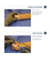
SUPERFICIAL EXPOSURE Make your incision. Make a longitudinal fascial incision over the center of the capitellum for the Kaplan approach. DEEP EXPOSURE Open the joint and gain access to the radial head. Limit distal dissection to protect the radial nerve.
Open the catalog to page 3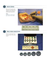
HEAD SIZING Remove the radial head measure them using the Radial Head Sizing Tray. If between radial head sizes, select the smaller. TRIAL HEAD SELECTION Select the Trial Head that
Open the catalog to page 4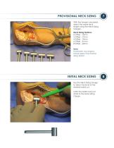
PROVISIONAL NECK SIZING With the forearm pronated, select the radial neck length using the Neck Sizing Gauges. Neck Sizing Options: 0 Offset - 15mm 2 Offset - 17mm 4 Offset - 19mm 6 Offset - 21mm 8 Offset - 23mm Note: If between two lengths, always select the shortest sizing option. INITIAL NECK SIZING Use the Neck Sizing Gauge to select the level of the desired radial cut. Mark the radial neck just distal to the Neck Sizing Gauge.
Open the catalog to page 5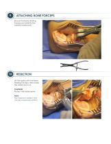
ATTACHING BONE FORCEPS Secure the Bone Holding Forceps just distal to the marked radial neck. RESECTION Lift the radius with the Bone Holding Forceps, then make the radial neck cut. CAUTION: Protect the radial nerve. Note: The maximum defect that can be corrected is 23mm.
Open the catalog to page 6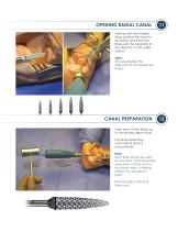
OPENING RADIAL CANAL Starting with the smallest Rasp, position the hand in pronation and insert the Rasp past the tuberosity in the direction of the radial styloid. Note: This will establish the trajectory for all subsequent Rasps. CANAL PREPARATION Insert each of the Rasps up to the etched depth mark. Continue broaching until cortical bone is encountered. Note: Each Rasp should be used as a broach. If the final Rasp used does not fully seat to the depth mark, a twisting motion can be used to ream. Note the size of the final Rasp used.
Open the catalog to page 7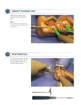
IDENTIFY PLANING LINE With the final Rasp fully seated, mark the highest spot. Note: This is the area to plane to ensure proper seating of the prosthesis. RASP REMOVAL To remove the Rasp, attach the Driver Extraction Tool to the Universal Handle and tap the striking plate.
Open the catalog to page 8
NECK PLANING Prepare the resected end of the radius using the Planer. Note: Spin the Planer before contacting the bone surface, then advance it lightly. FINAL NECK SIZING With the forearm pronated, confirm the final radial neck length using the Neck Sizing Gauges. Note: If between two lengths, always select the shortest sizing option.
Open the catalog to page 9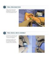
TRIAL STEM SELECTION Select the Trial Stem that corresponds to the final Rasp/Planer used and insert it into the prepared canal. TRIAL HEAD & NECK ASSEMBLY Assemble the Trial Head and Neck by threading the two components together. Thread the handle of the Neck Sizing Gauge into the Trial Head to facilitate loading onto the Trial Stem.
Open the catalog to page 10
TRIAL VALIDATION Assemble the Trial Head and Neck into the Trial Stem. Reduce the joint and assess the sizing of the trial components by manipulating the elbow through its full range of motion. Note: Ensure that the joint has not been over-stuffed. FLUOROSCOPIC CONFIRMATION Confirm a proper fit using fluoroscopy, then remove the trial components.
Open the catalog to page 11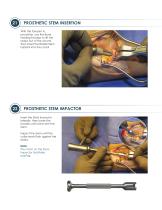
PROSTHETIC STEM INSERTION With the forearm in pronation, use the Bone Holding Forceps to lift the radius out of the wound, then insert the Radial Stem implant into the canal. PROSTHETIC STEM IMPACTOR Insert the Stem Impactor laterally, then lower the handle until in-line with the stem. Impact the stem until the collar seats flush against the radius. Note: The notch on the Stem Impactor facilitates loading.
Open the catalog to page 12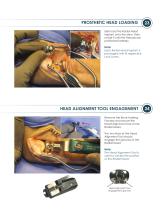
PROSTHETIC HEAD LOADING Side load the Radial Head implant onto the stem, then rotate it until the threads are positioned laterally. Note: Each Radial Head implant is packaged with its respective Lock Screw. HEAD ALIGNMENT TOOL ENGAGEMENT Remove the Bone Holding Forceps and secure the Head Alignment Tool to the Radial Head. The two tines of the Head Alignment Tool should engage the grooves of the Radial Head. Note: The Head Alignment Tool is used to control the position of the Radial Head. Head Alignment Tool engagement grooves
Open the catalog to page 13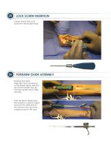
LOCK SCREW INSERTION Loosely thread the Lock Screw into the Radial Head. FOREARM GUIDE ASSEMBLY Keeping the Head Alignment Tool connected to the Radial Head, slide the rail of the Forearm Axis Jig into the handle until it snaps securely. With the elbow flexed and the forearm in neutral, adjust and lock the distal end of the Forearm Axis Jig to the marked fovea of the ulna.
Open the catalog to page 14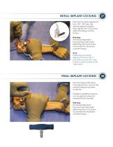
INITIAL IMPLANT LOCKING Pronate the Head Alignment Tool ~200 - 300 from the neutral forearm position, then tighten the Lock Screw while providing countertorque. Warning: The Head Alignment Tool must be used when tightening the Lock Screw to provide the necessary counter-torque. Note: Positioning the Head Alignment Tool in 300 of pronation ensures the Lock Screw is at the center of the “safe zone”. FINAL IMPLANT LOCKING Use the torque indicating T-Handle Driver to ensure the minimal torque has been achieved. If desired, additional torque can be gained using the Universal Driver Handle. Warning:...
Open the catalog to page 15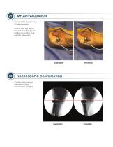
IMPLANT VALIDATION Remove the Forearm Axis Guide assembly. Manipulate the elbow through its full range of motion to confirm final implant alignment. FLUOROSCOPIC CONFIRMATION Confirm final implant alignment using fluoroscopic imaging.
Open the catalog to page 16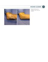
WOUND CLOSURE Repair soft tissues as needed, then close the incision.
Open the catalog to page 17
ALIGN® - Radial Head System - Cat.# ALN-RHA-SYS Catalog Number Radial Heads (CoCr) (Lock Screw Included) Catalog Number
Open the catalog to page 18
ALIGN®– Radial Head System ℞: For use by physicians only. Federal Law restricts this device to sale by or on the order of a physician. Failure to follow instructions may lead to patient injury. This package insert is designed to provide Instructions for Use of the ALIGN Radial Head System; it is not a reference to surgical techniques. Prior to use of the ALIGN Radial Head System the surgeon should become familiar with all information contained in this pamphlet. Symbols MATL: MATERIAL CoCr: MADE TI: TITANIUM ALLOY IN: QTY: SS, SST: STAINLESS STEEL DO NO REUSE (SINGLE USE ONLY) USE BY (EXPIRATION...
Open the catalog to page 19All Skeletal Dynamics catalogs and technical brochures
 GEMINUS ® Sales Sheet
2 Pages