
- Catalogs
- smart optics Sensortechnik GmbH
- Operating manual smart optics mini

Operating manual smart optics mini
Operating manual smart optics mini
Smart optics Sensortechnik GmbH offers first-level support through resellers and their Help Center, with the right to modify products and documentation.
Technical Data
The smart optics mini scanner measures 337 × 347 × 322 mm, weighs 9.5 kg, and operates on a 24 V DC power supply with a maximum consumption of 60 W. It uses stripe light triangulation and Blue Light LED technology for 3D measurements, with a resolution of 1.6 Mpx and accuracy of 6 µm as per ISO 12836.
Scope of Delivery
The package includes the scanner, a universal plate, a 3D calibration model, an external power supply, and a USB cable. A PC and screen are not included.
General Safety Information
Designed for dental technology applications, the scanner requires specialist knowledge in dental and CAD/CAM technology. Safety warnings include risks of electric shock, magnetic disturbances, and potential migraines or seizures from stripe light.
Components
The scanner features a 3D sensor, a removable rotary swivel unit, and an LED pressure switch, with accessories like a universal plate and a 3D calibration model.
Commissioning
The scanner should be placed on a stable, low-vibration table near the PC. Proper unpacking and connection procedures are crucial to avoid data transmission issues.
Maintenance and Cleaning
Regular maintenance and cleaning are essential to prevent inaccurate measurements or device defects. Users should contact support for cleaning electronic components.
Fault and Repair
First-level support is available for troubleshooting calibration failures, hardware problems, and connectivity issues.
Paid Extensions
Options for additional features and accessories, such as the impression holder and Comfort Mode, are available.
Disposal and CE Conformity
Instructions for disposing of packaging and the device are provided, along with CE conformity information.
Installation and Setup
Ensure the PC meets system requirements. Insert the scanner-specific data carrier into the PC, execute the setup file, and follow the Installation Wizard. Free upgrades should be installed in the same folder as the previous version.
Calibration
Calibration is crucial for accuracy, involving a 3D calibration model and specific data. Calibration data is unique to each scanner and should be stored securely.
Scanning Procedures
Different plates are used for scanning jaw models, with specific instructions for mounting. Reflective or dark objects should be matted with 3D scan spray. Articulators require specific positioning during scanning.
Maintenance and Cleaning
Regular calibration is necessary, with frequency depending on usage and conditions. Cleaning should avoid internal components and use appropriate materials.
Fault and Repair
Do not attempt self-repair; contact support for complex issues. Basic troubleshooting includes checking connections and calibration data accuracy.
Specifications and Procedures
Troubleshooting steps for poor scan results include checking lighting, ensuring material settings match, and verifying Quality settings.
Paid Extensions
Details on paid extensions like the Impression Holder, multiDie, and Comfort Mode are provided, with specific usage instructions.
Unlocking and Data Backup
Instructions for unlocking software functions using activation codes are provided, emphasizing secure storage.
Software Functions and Availability
Available software functions and their requirements are listed, including the need for specific adapters or plates.
Disposal Instructions
Guidelines for disposing of packaging and the device comply with European Directive 2002/96/EC for WEEE.
CE Conformity
The document confirms CE conformity, with contact information for the manufacturer.
Catalog excerpts

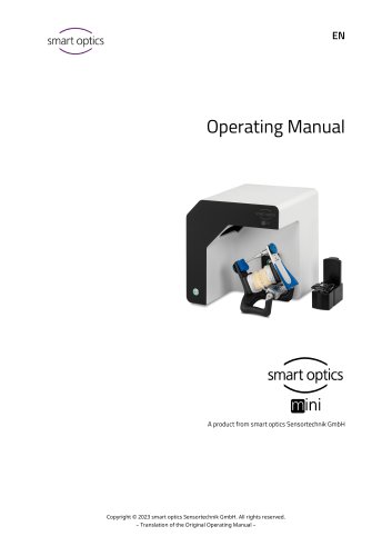
Operating Manual A product from smart optics Sensortechnik GmbH Copyright © 2023 smart optics Sensortechnik GmbH. All rights reserved. – Translation of the Original Operating Manual
Open the catalog to page 1
Legal notice FIRST-LEVEL SUPPORT FOR SMART OPTICS PRODUCTS Find a smart optics reseller in your region: Reseller locator www.smartoptics.de/en/dental/reseller-locator/ or via the contact form www.smartoptics.de/en/contact/ Support and first-level support: smart optics Help Center support.smartoptics.de CHANGES We reserve the right to make changes to the product and to this documentation. Current software version, catalog, flyer, instructions in the Download Center www.smartoptics.de BRANDS AND TRADEMARKS Adesso Split Amann Girrbach AG, AT-6842 Koblach exocad GmbH, DE-64293 Darmstadt Point Grey...
Open the catalog to page 2
Operating Manual smart optics mini
Open the catalog to page 3
Operating Manual smart optics mini 1 Explanation of Symbols Symbols on the Device Warning against electrical voltage Conformity of the scanner with EU directives USB connector Hollow plug connector Symbols in these Instructions Characters Signal Word Notice Danger Warning Caution Warning against possible: – Damage to property – Injuries (severe – moderate) – Injuries (minor) – Danger to life Simple list Numbered list Cross-reference (link) smart optics Help Center (external link) Paid extension (module/accessory) Software function released Software function
Open the catalog to page 4
Operating Manual smart optics mini Rotary swivel unit removable Material PUR, Acrylic, Aluminum Sheet Color black and white (matt) Power switch LED pressure switch External power supply 2.5m | AC 110/230V Operating temperature Storage temperature Relative humidity Stripe light triangulation, Blue Light LED 80 x 60 x 85 mm 6 pm 3D measurement technology Measuring field XYZ = max. object size Measurement accuracy acc. to ISO 12836 PC (minimum) CPU: i3 with 4 x 3.6 GHz | RAM: 16 GB | Port: USB 3.0 HDD: approx. 40 - 100 GB free | Graphics card RAM: 1 GB PC (recommended) CPU: i7 with 6 x 4.7 GHz|...
Open the catalog to page 5
Operating Manual smart optics mini smart optics mini, in addition: — Universal plate with adhesive pads — 3D calibration model — External power supply — USB cable (USB 3.0) Data carrier with: — Scan software dental scan — Calibration data (scanner-specific) PC and screen are not in the scope of delivery. smart optics mini was developed according to applicable safety standards and produced with protective measures. Nevertheless, some residual risks cannot be ruled out. — the three-dimensional optical measurement of human jaw models/jaw impressions, — Reconstructions and archiving in prosthetics...
Open the catalog to page 6
Operating Manual smart optics mini 4.3 User Qualification To commission, install and operate the scanner, you need specialist knowledge of dental technology, in particular CAD/CAM technology, as well as knowledge of the scanner from operating instructions, instruction or training. Protection against Injuries WARNING Electric shock, burns Electric shock and burns can be caused by: defective electrical devices or cables (e.g. lack of insulation), wetness on electricity-carrying parts, electrical connections without earthing, overloaded wall sockets and lines. Use electrical equipment...
Open the catalog to page 7
Operating Manual smart optics mini CAUTION Pulling in of garments, jewelry, hair Loose garments, jewelry or hair can be pulled in by automatically moving components. At the scanner workstation, avoid scarves, ties, long chains, open long hair, etc. If something is pulled in, turn off the scanner immediately and disconnect the power supply from electricity. Protection against Damage to Property NOTICE Inaccurate measurements or device defect due to mechanical damage, soiling or incorrect cleaning of electronic components All electronic components, in particular the 3D sensor (LED projector,...
Open the catalog to page 8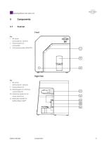
Operating Manual smart optics mini 2 Rotary swivel unit (removable) 3 LED pressure switch (ON/OFF) Right Side Key 1 3D sensor (LED projector, camera) 2 Rotary swivel unit 2a Retaining pins (2 at the top, 2b Attachment plate for the rotary swivel unit 2c Base plate suitable for Splitex/Adesso Split®
Open the catalog to page 9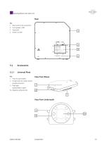
Operating Manual smart optics mini Rear Key 1 Rear panel screw connection 2 Fixing hooks for rubber bands (simple occlusion) 3 Plate type Splitex/Adesso Split® 3a Magnetic adhesive disc View from Above View from Underneath 3a
Open the catalog to page 10
Operating Manual smart optics mini 1 Hemispheres (for distance measurement) 2 Cylinders (for height measurement) 3 Label with model number and reference values The scanner must be next to the PC, preferably on a laboratory table or professional work table. Laboratory, factory, manufacturing Indirect light opaque, stable, low vibration 337 x 347 x 322 mm (W x H x D) 2 x 9.5 kg Inaccurate measurements or device defect due to non-compliance with workplace requirements > Avoid reflections on the measurement object. Protect the scan area in intense ambient light (artificial light, sunlight), e.g....
Open the catalog to page 11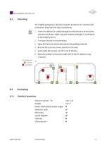
Operating Manual smart optics mini The original packaging is the best transport protection for scanners and accessories. Keep them for later transporting. 1. Check the delivery for visible damage and discoloration on the shock indicators (indicator label). Log and complain damages in accordance to the shipping terms. 3. Open the box from above and remove the padding material. 4. Remove the accessory boxes (stored on the side). 5. Grab under the scanner and lift it out of the box. 6. Place the scanner on the work table next to the PC (distance max. Carrying points Q = allowed |~| = prohibited...
Open the catalog to page 12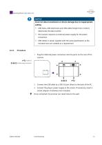
Operating Manual smart optics mini NOTICE Incorrect data transmission or device damage due to inappropriate cabling USB Hubs, USB extensions and USB cables longer than 2 meters deteriorate the data transfer. The scanner requires an external power supply for the power connection. USB cables or power supplies with the same specification as the included ones are suitable as a replacement. Procedure 1. Plug the USB and power connectors into the ports on the rear of the scanner. USB 3.0 Hollow plug connector 2. Connect the USB cable to a USB 3.0 port (blue) on the back of the PC. 3. Connect...
Open the catalog to page 13All Smart optics Sensortechnik GmbH catalogs and technical brochures
 Operating manual Vinyl series
95 Pages
 Flyer Vinyl High Resolution
2 Pages
 smart optics mini
2 Pages
 Vinyl High Resolution
3 Pages
 Vinyl UXD
2 Pages

Archived catalogs
 Audiology
22 Pages
 AUDIOLOGY CATALOGUE
24 Pages
 scanBox pro
1 Page
 Activity Scanner
8 Pages
 duo scan
4 Pages
 ds Production
4 Pages
 mono Scan
4 Pages
 Activity 710
1 Page
 software dentprogress 2015
6 Pages
 Activity 300
1 Page
 Activity 885 Mark 2
1 Page
 scanBox
1 Page
- Visualization software
- Windows software
- Dental software
- Design software
- Capture software
- Smart optics 3D scanner
- 3D dental scanner
- Server-based software
- 3D software
- CAD software
- Smart optics STL 3D scanner
- Smart optics benchtop 3D scanner
- Smart optics LED 3D scanner
- Smart optics PLY 3D scanner
- Orthodontic software
- Dental laboratory software
- Color 3D scanner
- Structured light 3D scanner
- Medical industry 3D scanner
- High-resolution 3D scanner