- Catalogs
- Smith & Nephew
- BIRMINGHAM HIP
- Products
- Catalogs
- News & Trends
- Exhibitions
BIRMINGHAM HIP
1 /32Pages
BIRMINGHAM HIP
1 /32Pages
Catalog excerpts

Surgical Technique
Open the catalog to page 1
BIRMINGHAM HIP™ Resurfacing System Nota Bene The following technique is for informational and educational purposes only. It is not intended to serve as medical advice. It is the responsibility of treating physicians to determine and utilize the appropriate products and techniques, according to their own clinical judgment, for each of their patients. For more information on the product, including its Indications for Use, contraindications, preparation and product safety information, please refer to the product’s label and the Instructions for Use (IFU) for the product
Open the catalog to page 2
The surgical approach The BIRMINGHAM HIP™ Resurfacing device may be implanted through all normal surgical approaches. The posterior approach is described in this operative technique.
Open the catalog to page 3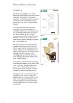
Preoperative planning Templating BHR™ template sets (Figure 1) are used to determine component size and correct implant positioning. The position of the femoral component is a most important pre-operative consideration. Varus positioning must be avoided and slight valgus is recommended (Figure 2). To achieve optimal femoral component positioning, place the appropriate BHR template onto the X-ray. Once happy with the size chosen the medial head-neck-junction may be identified to set up the correct template positioning. This is aided by using the cut out section on the template which allows implant...
Open the catalog to page 4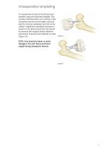
Intraoperative templating An assessment is made of the femoral neck diameter using the head/neck template. This provides vital information as to minimum head component size that can be safely used and also the minimum acetabular size that can be utilised. If significant osteophyte formation is present on the femoral neck then this should be removed with rongeurs before definitive assessment of femoral neck diameter is made (Figure 3,4). NOTE: Care should be taken to avoid damage to the soft tissue and blood supply during osteophyte removal.
Open the catalog to page 5
Acetabular preparation If the anteroinferior capsule is tight an antero inferior radial capsulotomy is made in line with the psoas tendon. A H ohmann retractor is placed inferior to the radiographic teardrop. The acetabular labrum, transverse ligament and ligamentum teres are excised revealing an unencumbered view of the complete acetabulum and a view of the true floor of the acetabulum. Sequential reaming with hemispherical acetabular reamers is then performed and in normal consistency bone, reaming proceeds to 2mm less than the definitive acetabular component to be inserted (Figure 5). Figure...
Open the catalog to page 6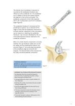
The desired size of acetabular component is mounted on the acetabular introducer and offered up to the acetabular rim. The acetabular cup is rotated so that its anti-rotation splines are adjacent to the ischium and pubis. The acetabular component is then fully impacted with 15-20˚ of anteversion and 40-45˚ inclination angle (Figure 8). The acetabular introducer is removed and the polyethylene impactor cap is retracted at this stage to check that the acetabular component is correctly inserted. Adjustment of the cup position can be made by re-attaching the acetabular introducer. Cup removal is...
Open the catalog to page 7
Curved Cup Introducer These instructions provide important information regarding assembly and wiring for use of the BHR™ Curved Cup Introducer. NOTE: This Curved Cup Introducer is for use with BHR Resurfacing cups only.
Open the catalog to page 8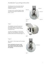
Acetabular Cup wiring instruction The following is the recommended method of attaching the Curved Cup Introducer to the acetabular component. To ensure correct component fixation, please note that the wire loops are specified as wire loops 1, 2 and 3. Wire loop 1 Wire loop 3 Wire loop 2 Step 1 The acetabular component is placed over the threaded spigot on the face plate of the introducer, with the introducer passing through wire loop 1. To ensure correct alignment, check that the fixation fins of the acetabular component are positioned either side of the device (Figure 1, 2). Figure 2 Step 2...
Open the catalog to page 9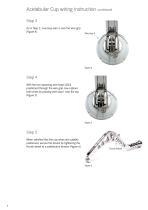
Acetabular Cup wiring instruction continued Step 3 As in Step 2, now loop wire 3 over the wire grip (Figure 4). Step 4 With the two opposing wire loops (2&3) positioned through the wire grip now capture both wires by passing wire loop 1 over the top (Figure 5). Step 5 When satisfied that the cup wires are suitably positioned, secure the device by tightening the thumb wheel to a satisfactory tension (Figure 6). Thumb Wheel
Open the catalog to page 10
X-Bar X-Bar (Figure 7) The X-Bar is attached to the curved Cup Introducer (Figure 8). With the patient positioned correctly align the impactor so that the appropriate bar on the guide, left or right, is parallel to the longitudinal axis of the patient while the vertical bar is perpendicular to the floor. This will provide approximately 40-45˚ of abduction and 15-20˚ of anteversion (Figure 9). Surgical Tip • Target acetabular component orientation for optimal bearing function; 40-45˚ of abduction 15-20˚ of anteversion <45˚ combined stem/cup anteversion
Open the catalog to page 11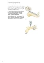
Femoral preparation The desired position of the femoral alignment pin will be known from the pre-operative templating. Identify the tip of the greater trochanter through the tissues with a spinal needle. A ruler is used to measure the desired distance down from the tip of the greater trochanter (Figure 1) and the alignment pin is inserted through the vastus lateralis fibres. The front and back of the femoral shaft are felt and pin insertion is then started in a transverse direction into the mid-lateral cortex (Figure 2).
Open the catalog to page 12
After the outer cortex is breached the drill is angulated so that the alignment pin is directed towards the femoral head (Figure 3). The alignment pin is left protruding 5mm above the outer fibres of vastus lateralis. NOTE: It is recommended that “Pin in Femur” is placed on the nurse’s swab count board. Using the McMinn Alignment Guide The appropriate head implant size is set up on the head centre stylus. The alignment guide (Figure 4) is hooked onto the alignment pin and the leg fully internally rotated to deliver the femoral head into the centre of the wound.
Open the catalog to page 13All Smith & Nephew catalogs and technical brochures
 ANTHEM 2024
40 Pages
 FREEDOM
16 Pages
 SALTO TALARIS
48 Pages
 polarstem
28 Pages
Archived catalogs
 Locking Large Fragment Overview
32 Pages
 Locking Small Fragment Overview
68 Pages
 Rediscover normal
4 Pages
 TWINFIX ULTRA HA and PK
2 Pages
 TRIGEN™ INTERTAN
12 Pages
 EVOS SMALL Resources
12 Pages
 NAVIO Message Brochure
8 Pages
 Small footprint, big impact
8 Pages
 TAYLOR SPATIAL FRAME◊
8 Pages
 Recertification Program
8 Pages
 anthem
4 Pages
 Ordering information
1 Page
 BST-CarGel ®
20 Pages
 RAPID RHINO™ NASASTENT™
6 Pages
 clancy anatomic cruiciate
2 Pages
 Electrosurgery
20 Pages
 Powered Instruments
11 Pages
 Shaver Systems
7 Pages
 Knee
Knee73 Pages
 HIP
HIP21 Pages


- Bone plate
- Compression plate
- Metallic compression plate
- Locking compression plate
- Wound care
- Medical kit
- Surgery electrode
- Electrosurgical electrode
- Surgical system
- Reusable electrode
- Cutting electrosurgical system
- Coagulation electrosurgical unit
- Endoscopy forceps
- Monopolar electrode
- Wound dressing
- Sealing forceps
- Straight electrode
- Bandage
- Proximal compression plate
- Coagulation electrode