ULC Series
1 /23Pages

ULC Series
1 /23Pages
Catalog excerpts
Push-Pull Connectors for Nuclear Industry Push-Pull Connectors for Nuclear Industry
Open the catalog to page 1
The latching of plug into the receptacle Is achieved by a simple axial pushing on the outer shell. Connection cannot be broken by pulling the cable or any other parts of the plug than the outer shell. Receptacle and plug sections 3
Open the catalog to page 3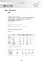
General description Shells • Easy to use : "PUSH-PULL" latching • Watertight to 2 bars, mated connectors • Brass shells with Nickel + Chrome plating, or stainless steel for special applications nuclear, corrosive fields etc... (Stainless steel shells for remote manipulation) • Alternative insulators to suit conditions (temperature, radiation, etc...) • Gold and nickel plated contact, to solder • Mechanical keying • Pre-guiding available on remote manipulation versions • Four shell sizes (I, III, IV, V) for multipin connectors • O'ring : . standard; nitrile for brass shell, epdm for stainless...
Open the catalog to page 4
Reference example: Remote manipulated straight plug, socket contacts, size III, A contacts, brass ULC series standard Insulator, cable outer diameter = 10,6 mm, PI Keying. Shells: (see pages 7 and 8) FET F III M4 ULCL S 106 PI FET : Remote manipulated straight plug RE : Round receptacle, front mounting RECSC : Square receptacle with cable clamp RES : Round salient receptacle, rear mounting RESC : Round receptacle with cable clamp, front mounting RESSC : Round receptacle with cable clamp, rear mounting PCE : Cable receptacle TRE : Feed through bulkhead FETFP : Remote manipulated straight plug...
Open the catalog to page 5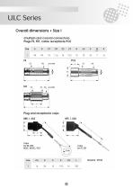
Overall dimensions • Size I (multipin and coaxial connectors) Plugs FE, FET, cable receptacle PCE Plug and receptacle caps BRE. I. 802 BFE. I. 802
Open the catalog to page 12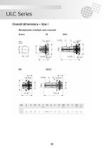
Round Pane
Open the catalog to page 14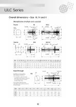
Panel cut-out * socket side fork, please consult us. For multipin, feed through ore fitted with socket contacts For coaxial, feed through ore fitted with socket contacts
Open the catalog to page 15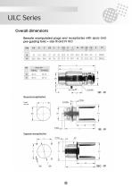
Overall dimensions Remote manipulated plugs and receptacles with spurs and pre-guiding forks • size III and IV ULC Size 0A B C 0D E F 0G H J M 0P 0R 0S U 0T
Open the catalog to page 16
Assembly with coupling lever Force Mating 150N±15 Gearing down lever Ref. : OUT FE GVP GC ULC Lever gear ratio : 1/3.
Open the catalog to page 17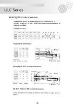
Available in size III for three types of 75Q. cable (A - B or C) For any other 75Q. or 50Q, state the cable type at the end of the part number Cable type description : Plug overall dimensions Receptacle RESC overall dimensions Overall dimensions of these shells are standard, refer to tables on pages 14 and 16 (size III).
Open the catalog to page 18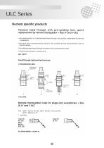
The replacement of a deteriorated feed through can be fully undertaken by remote manipulator. • No leak from contaminated area to the outside during replacement due to special design. The deteriorated feed through remains in the contaminated area Positive clamping by a locking fork. Feed through replacement process CONTAMINATED AREA Deteriorated receptacle COLD SIDE ': shell size For fufher details : consult us
Open the catalog to page 19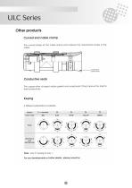
The curved shape at the cable clamp end reduces the mechanical strains in the cable Curved end cable clamp The copper-silver charged rubber gasket and receptacle O ring improve the shell to shell conductivity. Color code Note : only PI keying for size 1. For any developments or further details : please consult us.
Open the catalog to page 20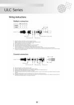
5 Back shell with cable clamp Strip the cable In accordance with the diogram above Note : The wires have to be cut to the position of the solder buckets Slide the parts 5.4.3 and 2 over the cable in order Slip a heat strlnk tube on each conductor Soft solder wires Into contacts, starting at the center of Insulator Slide the heat shrink tubes against insulator and heat them Mount the spacer n°2 on the Insulator. Grease slightly the Insulator O' ring Use the mounting tools to mount and to rotate the set into the shell in order to find the correct polarization Remove the tool, slide forward the...
Open the catalog to page 21
Continuity contact Inner ring Ground contoct i Cable seal Outer solder Insulator bearer Sort soldering Continuity contact insulator bearer insulating washer Inner ring Insulator block Insulating washer i Outer solder ring Soft soldering Cable seal Back shell Mount the parts 9,8 and 7 over the cable in the correct order Strip the cable end at Max. dimensions indicated above Insert the ground contact n° 5 fitted with the insulating washer n°6 under the outer braid A. slide back the ring n°7 Into contact with part 5. then soft solder both parts in 4 spots Slide the part 4 over the inner braid B....
Open the catalog to page 22
Copyright SOURIAU SOURIAU Connection Technology
Open the catalog to page 23All SOURIAU catalogs and technical brochures
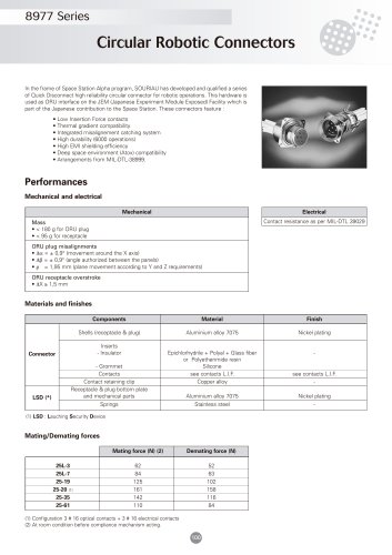 8977 Series
8 Pages
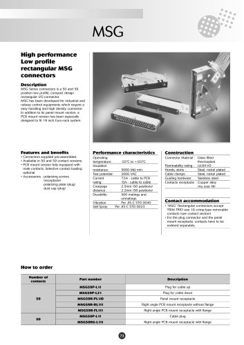 MSG
MSG8 Pages
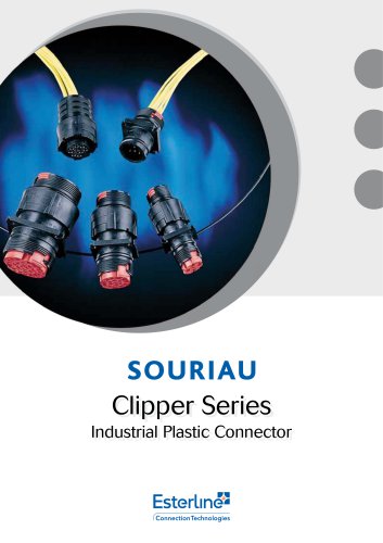 Clipper Series
28 Pages
 Self-seating Connector Accessories
174 Pages
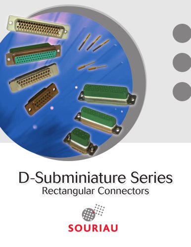 D-Subminiature Series
30 Pages
 JDX Series - Breakaway Connector
36 Pages