- Catalogs
- Standard Imaging
- Ii Dosimetric Characterization Output Verify
Ii Dosimetric Characterization Output Verify
1 /17Pages

Ii Dosimetric Characterization Output Verify
1 /17Pages
Catalog excerpts
Dosimetric characterization and output verification for conical brachytherapy surface applicators. Part II. High dose rate 192Ir sources Regina K. Fulkerson, John A. Micka, and Larry A. DeWerd Citation: Medical Physics 41, 022104 (2014); doi: 10.1118/1.4862506 View online: http://dx.doi.org/10.1118/1.4862506 View Table of Contents: http://scitation.aip.org/content/aapm/journal/medphys/41/2?ver=pdfcov Published by the American Association of Physicists in Medicine
Open the catalog to page 1
Dosimetric characterization and output verification for conical brachytherapy surface applicators. Part II. High dose rate 192 Ir sources Regina K. Fulkerson,a) John A. Micka, and Larry A. DeWerd Department of Medical Physics, University of Wisconsin–Madison, Madison, Wisconsin 53705 (Received 31 July 2013; revised 20 November 2013; accepted for publication 9 December 2013; published 23 January 2014) Purpose: Historically, treatment of malignant surface lesions has been achieved with linear accelerator based electron beams or superficial x-ray beams. Recent developments in the field of brachytherapy...
Open the catalog to page 2
Fulkerson, Micka, and DeWerd: Surface applicator output verification F IG . 1. VariSource iX and GammaMedplus iX. (a) VariSource iX source geometry, units in mm. (b) GammaMedplus iX source geometry, units in mm. Images courtesy of Rasmussen et al. (Ref. 14). Varian offers two types of applicators manufactured out of a stainless-tungsten alloy (Fig. 2) for use with the GammaMedplus iX and the VariSource iX. One applicator type positions the source parallel to the treatment surface inside a source guide tube with a nominal source to surface distance (SSD) of 12.5 mm. The other applicator positions...
Open the catalog to page 3
Fulkerson, Micka, and DeWerd: Surface applicator output verification F IG . 3. Schematic of source dwell positions within Varian surface applicators. (a) Varian surface applicator with VariSource iX. (b) Close-up of VariSource iX in Varian surface applicator showing dwell index. (c) Varian surface applicator with GammaMedplus iX. (d) Close-up of GammaMedplus iX in Varian surface applicator showing dwell index. While standard dosimetry protocols exist for brachytherapy sources and low-energy external photon beams, the geometric and scatter conditions observed with the HDR 192 Ir and electronic...
Open the catalog to page 4
Fulkerson, Micka, and DeWerd: Surface applicator output verification determined as Kair = M · NK · P elec · PTP ·P cham · PPOM , where the air kerma, Kair is determined through: M is the measured charge reading over a collecting period; Pelec is the electrometer calibration coefficient; PTP is the correction for ambient temperature and pressure; and NK is an applicatorspecific calibration coefficient. Pcham = Kair vol is a chamber Kcham replacement factor, where Kair vol is the Monte Carlo calculated kerma to air-volume at the point of measurement and Kcham is the Monte Carlo calculated kerma to...
Open the catalog to page 5
Fulkerson, Micka, and DeWerd: Surface applicator output verification 2.B. Correction factors for determination of absorbed dose to water F IG . 4. Modified seven-distance apparatus with surface applicator. Positioning of the applicator and chamber was achieved with two alignment lasers. Once a nominal distance of 10 cm between the applicator exit window and center of the ionization chamber was achieved, charge readings were collected with a Standard Imaging Supermax electrometer at distances ranging from 5 to 30 cm from the exit window of the surface applicator. Unlike the traditional seven-distance...
Open the catalog to page 6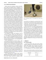
Fulkerson, Micka, and DeWerd: Surface applicator output verification 2.C.2. Relative dose distributions Relative surface dose distributions, profiles, and distributions at depth were measured using a combination of radiochromic films and TLDs for all source and applicator combinations. Details regarding the experimental methods for the TLD and film measurements can be found in Part I. Solid poly-methyl methacrylate (PMMA) ρ = (1.18 ± 0.01) g cm−3 phantoms were constructed to hold TLD-100 microcubes and position radiochromic film for surface and at-depth measurements. Monte Carlo simulations in MCNP5...
Open the catalog to page 7
Fulkerson, Micka, and DeWerd: Surface applicator output verification TABLE II. Air-kerma rate for the Varian surface applicators with the VariSource iX. Chamber measured air-kerma rate (mGy • s-1) Exradin A3 54.6 55.1 54.5 55.1 TABLE IV. Measured and calculated air-kerma rate at the surface of the 30 mm diameter applicator and GammaMedplus iX. Values have been normalized to a reference date. Method Air-kerma rate (cGy) % difference Monte Carlo calculated 6.05 Table II shows the measured air-kerma rate at the exit window for each Varian surface applicator with the VariSource...
Open the catalog to page 8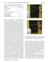
Fulkerson, Micka, and DeWerd: Surface applicator output verification TABLE VI. Uncertainty budget for Exradin A3 measurements of air-kerma rate for the Varian surface applicators with the GammaMedplus iX. Component Type A % Type B % Chamber position relative to applicator exit window 1.2 Source position within applicator 0.31 0.16 Expanded uncertainty (k = 2) 4.2 applicator was dependent on the afterloader deployment mechanics as described in Sec. 1.A. The manufacturer quotes a ±1 mm uncertainty in the source position for any source/applicator combination. However, this broad...
Open the catalog to page 9
Fulkerson, Micka, and DeWerd: Surface applicator output verification 022104-9 TableVII. Uncertainty budget for Exradin A20 measurements of air-kerma rate for the Varian surface applicators with the VariSource iX. Table IX. Calculated Pcham for the Exradin A20 and the surface applicators of interest. These values were derived from MCNP5 simulations. Varian surface applicators with VariSource iX Diameter (mm) Pcham Varian surface applicators with GammaMedplus iX Applicator diameter (mm) Pcham Component Type A % Type B % Chamber positioning on applicator exit window 0.04 Source position...
Open the catalog to page 10
Fulkerson, Micka, and DeWerd: Surface applicator output verification TABLE X. Calculated PDw values for the surface applicators of interest. PDw : Varian surface applicators with VariSource iX Depth (mm) Diameter (mm) PDw : Varian surface applicators with GammaMedplus iX Depth (mm) Diameter (mm) 30 35 40 45 measured calculated measured calculated F IG . 7. Percentage depth dose curves in water for the Varian surface applicators and VariSource iX. Medical Physics, Vol. 41, No. 2, February 2014
Open the catalog to page 11All Standard Imaging catalogs and technical brochures
 QA BeamChecker Plus
7 Pages
 QA CrossChecker
2 Pages
 QA StereoChecker
2 Pages
 Jacob Gersh, PhD, DABR AAPM Talk
19 Pages
 SuperMAX
8 Pages
 MAX 4000 Plus Electrometer
2 Pages
 CDX 2000B Electrometer
2 Pages
 Luthmann QA Tool
2 Pages
 IVB 1000 Well Chamber
2 Pages
 Blue Water Phantom
2 Pages
 Virtual Water Phantom
1 Page
 ARC QA Phantom
2 Pages
 IMRT
IMRT2 Pages
 MIMI
MIMI2 Pages
 Lucy 3D QA
12 Pages
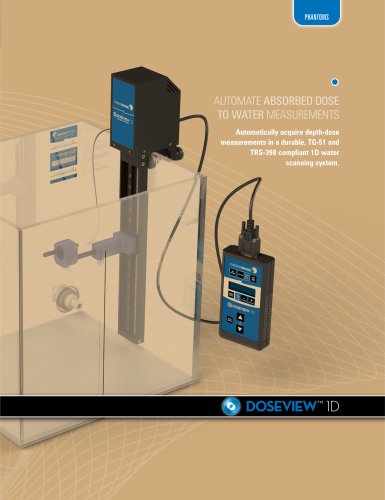 DoseView 1D
4 Pages
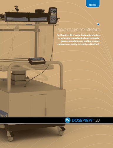 DoseView 3D
12 Pages
 RAy Datasheet
2 Pages
 RT Workspace Brochure
10 Pages
 Dosimetry Check Datasheet
2 Pages
 IMSure Brochure
10 Pages
 PIPSpro Software Brochure
12 Pages


- Analysis software
- Tablet computer software
- Radiology software
- Tablet PC software
- Test phantom
- Reporting software
- Monitoring software
- Planning software
- Cloud-based software
- Automated software
- Software module
- Measurement software
- Tomography test phantom
- Web-based software
- CT scan test phantom
- Import software
- Test software
- General purpose test phantom
- Medical software on site
- CT software