Reflex®

Reflex®
The Reflex Hybrid Anterior Cervical Plating System is designed to enhance anterior cervical discectomy and fusion by providing temporary postoperative stability. It combines constrained and semi-constrained systems to accommodate various cervical spine pathologies, offering versatility and ease of implantation.
The system features a low-profile plate made from Ti-6Al-4V alloy to minimize soft tissue irritation. It includes fixed and variable angle screws for a range of motion and load sharing, with a locking ring mechanism for secure screw placement.
Patients are positioned supine with the head slightly turned. Incisions vary based on the number of levels treated, with a preference for the left side to minimize nerve injury risk. The procedure follows a discectomy or corpectomy with graft insertion.
Plate sizing is crucial and measured between vertebrae centers. A universal plate holder aids in size confirmation. Plates can be contoured using a plate bender, avoiding bending near screw holes to prevent compromising the locking mechanism.
Preparation varies by screw type, with options for drilling, tapping, and using a punch awl. Guides ensure proper angulation and secure locking. Drill bits are specific to the system to prevent over-drilling.
Screws are inserted using various drivers, with guides ensuring correct trajectory. The system includes self-tapping and self-drilling screws, with color-coded identification for easy selection. Proper angulation is critical for secure locking.
- Collet Screwdriver Usage: The collet sleeve must be open to load screws. The self-centering pin of the screwdriver is inserted into the bone screw's head, and the driver handle is rotated until the cruciform geometry aligns. The collet sleeve is then lowered to secure the screw.
- Final Tightening: The final tightening screwdriver, identified by its gold anodized shaft, is used to lock screws into the ring. It requires minimal torque, not exceeding a quarter turn once the screw is beneath the ring.
- Screw Removal: The screw extractor and revision driver are used for removing screws. The extractor uses an outer sleeve for counterforce, while the revision driver bypasses the locking ring with a narrow tip.
The Collet Screwdriver is a three-piece design that must be disassembled for sterilization and stored in the Reflex® Hybrid System Container. The collet sleeve should be in the open position during storage to maintain retention.
The document lists various sizes of anterior cervical plates and bone screws, including variable and fixed angle, self-tapping, and self-drilling screws. It also details the instruments used, such as drill guides, screwdrivers, and extractors.
- Indications: The ACP Systems are intended for anterior intervertebral screw fixation of the cervical spine from C2 to T1 for conditions like degenerative disc disease, trauma, tumors, and more.
- Contraindications: Include marked local inflammation, compromised bone stock, and metal sensitivity, among others.
- Patient Information: Surgeons must inform patients about the limitations and risks associated with the device, including the potential need for future replacement and the impact of strenuous activities.
Considerations include the patient's occupation or activities that may stress the implant, which could increase the risk of device failure.
Catalog excerpts

Reflex® Hybrid Surgical Technique Anterior Cervical Plating System
Open the catalog to page 1
Patient Positioning and Exposure 6 Implant Selection and Preparation 6 Bone Screw Hole Preparation 8 Bone Screw Insertion 10 Bone Screw Removal 18 Anterior cervical discectomy and fusion remains one of the most successful surgical procedures, and the application of a plate to provide temporary postoperative stability has gained widespread acceptance as the “gold standard” of care. Anterior cervical plating systems continue to evolve and incorporate contemporary biomechanical understanding of the demands placed on these devices. Currently available anterior cervical instrumentation...
Open the catalog to page 2
The Reflex® Hybrid ACP System offers a low-profile anterior cervical plate along with a selection of bone screw types to allow for a wide variety of constructs. Depending on the component combination, the system can accommodate both semi-constrained and rigid bone screw fixation philosophies. Instrument options further enhance surgical technique versatility by matching surgeon preference regarding approach and screw pathway preparation. The Reflex® Hybrid plate, made from a Ti-6Al-4V alloy, is 2.1mm thick to help reduce soft tissue irritation and may provide a suitable option for small stature...
Open the catalog to page 3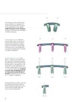
The neutral axis of the end-hole bone screws is defined as 8° cephalad or 8° caudal from perpendicular to the plate in the sagittal plane as well as 8° of medial convergence in the axial plane. All types of screws have the same degree of medial convergence. Fixed angle bone screws, which are used if a rigid construct is desired, are inserted into the plate in the neutral position as described above, and they remain in this position under loading. Fixed bone screws in the middle holes are inserted perpendicularly to the plate (at 0 degrees angulation). Variable angle bone screws, which allow +/-...
Open the catalog to page 4
Both fixed and variable screws are offered as self-tapping, which feature a cutting flute and a less aggressive screw tip, and self-drilling, which have been designed with a sharp tip for insertion without prior drilling. The individual screw families have been Screw Type Variable Angle Fixed Angle color coded for easy identification: 4.0mm Self-Tapping 4.5mm Self-Tapping l^i“ ir/LiVl'A j-r^r-T r' The Reflex® Hybrid plates and screws represent a complete system, which is separate and not interchangeable with the original Reflex™ ACP system implants. Refer to the indications and...
Open the catalog to page 5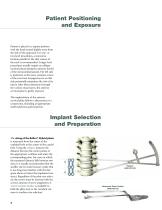
Patient Positioning and Exposure Patient is placed in a supine position with the head turned slightly away from the side of the approach. For one- or two-level procedures, a transverse incision parallel to the skin creases of the neck is recommended. Longer level procedures usually require an oblique incision placed along the anterior border of the sternocleidomastoid. The left side is preferred, as the more constant course of the recurrent laryngeal nerve on this side potentially minimizes the risk of its injury. After blunt dissection through the various tissue layers, the anterior cervical...
Open the catalog to page 6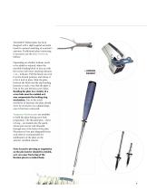
The Reflex® Hybrid plate has been designed with a slight sagittal and axial bend for optimal matching of a patient’s anatomy. If additional plate contouring is necessary, use the plate bender as follows: Depending on whether lordosis needs to be added or reduced, adjust the movable bending block to face up with the correct side (laser marking indicates + or - lordosis). Pull the block out, turn it to the desired position, and release it to let it lock in place. Slide the plate between the block and the top bending hammer in such a way that the plate is bent in the area between screw holes. Bending...
Open the catalog to page 7
Screw Hole Preparation Depending on the type of a screw selected for a particular procedure, the following options are available for screw hole preparation. Single Barrel Double Barrel Screw insertion Screw insertion Screw insertion In all procedures above, optional tapping would precede screw insertion, if desired. Note: To ensure proper locking of the bone screws, freehand insertion of the bone screws is not recommended and can result in backout of bone screws if not properly aligned. 8 Screw insertion
Open the catalog to page 8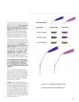
While certain instruments - such as the awl, drills, tap, and the screwdriver - are used for all types of bone screws, the drill guides and punch awl must correspond to whether fixed or variable angle bone screws will be implanted. The variable and fixed angle guides can be identified by their blue and purple handles, respectively. The punch awl handle is not screw-specific; however, the fixed and variable angle awl sleeves can be identified by the appropriate laser marking. Both the fixed and the variable angle guide instruments direct the screw trajectory within the range that ensures optimal...
Open the catalog to page 9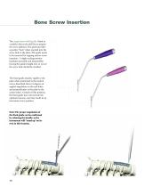
Bone Screw Insertion The single-barrel drill guide (fixed or variable) directs the drill bit to prepare the screw pathway. The guide provides a positive “lock” when inserted into the screw hole in the plate. The guide needs to be removed for tapping and/or screw insertion. A slight rocking motion facilitates assembly and disassembly; forcing the guide straight into or out of the screw hole should be avoided. The fixed guide attaches rigidly to the plate when positioned in the neutral axis as described above (8 degrees of sagittal angulation on the end holes, and perpendicular to the plate in...
Open the catalog to page 10
The double-barrel drill guide (fixed or variable) allows for both screw holes at a certain plate level to be prepared at the same time. The barrels are directed at 8 degrees of convergence for both screw types (fixed and variable); while the variable guide allows for sagittal angulation, the fixed guide is positioned rigidly in the neutral axis. Rocking the instrument from left to right facilitates assembly, i.c. attaching the left barrel first and then allowing the right barrel to come into position. Reversing the motion will ensure smooth disengagement of the guide. Similarly to the single-barrel...
Open the catalog to page 11All Stryker catalogs and technical brochures
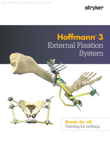 Hoffmann® 3
2 Pages
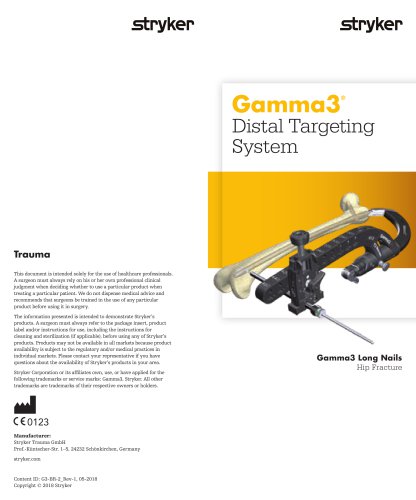 Gamma3
2 Pages
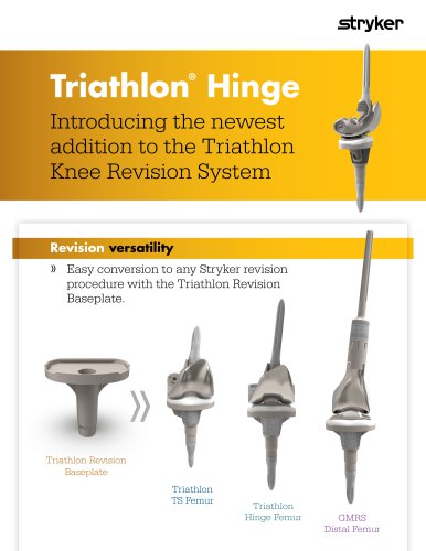 Triathlon Hinge Sell Sheet
2 Pages
 ICU Brochure
6 Pages
Archived catalogs
 C-Arm T racking System
2 Pages
 ACL Instrumentation Brochure
6 Pages
 System 7
7 Pages
 System 7 Precision
2 Pages
 System 7 Battery
2 Pages
 System 7 Sterilization Case
2 Pages
 CD4 & SABO2 Family
5 Pages
 Gamma3 Trochanteric Nail 180
48 Pages
 Gamma3 Long Nail R2.0
48 Pages
 Gamma3 Fragment Control Clip
6 Pages
 Gamma3 U-Blade Lag Screw
18 Pages
 trident
12 Pages
 GMRS
GMRS13 Pages
 Scorpio ®Knee TS
6 Pages
 CBC II
2 Pages
 the Mill
2 Pages
 Gamma3 T
6 Pages
 Label Changes
2 Pages
 SmartTip ™
3 Pages
 SDC 3
SDC 32 Pages
 System 7 Family
7 Pages
 Mixevac III
2 Pages
 InterPulse - Orthopaedics
4 Pages
 Neptune 2
2 Pages
 Neptune E-SEP
2 Pages
 Right Angled Screwdriver
8 Pages
 Universal Neuro III
10 Pages
 EasyClip
2 Pages
 Asnis ® Micro Xpress
2 Pages
 S3 MedSurg Bed
8 Pages
 Stryker NAV3i
4 Pages
 Cast Cutter
2 Pages
 Cast Vac
2 Pages
 Revolution
6 Pages
 SmartPump
2 Pages
 Disposable Cuff
2 Pages
 Patient Education
2 Pages
 Reusable Cuff
2 Pages
 SurgiCount
4 Pages
 OASYS®
44 Pages
 Escalate®
16 Pages
 Stryker Biologics
46 Pages
 Aero® -C
6 Pages
 Dynatran
13 Pages
 Aviator™
2 Pages
 AVS Anchor® -C
2 Pages
 Humeral Nailing System
44 Pages
 Luxor
Luxor4 Pages
 OrthoMap®
4 Pages
 ENT navigation system
7 Pages
 AxSOS 3® Titanium
36 Pages
 Smart Equipment Management
3 Pages
 Prime TC®
4 Pages
 TruRize™ Clinical Chair
4 Pages
 TruRize® Clinical Chair
2 Pages
 VariAx® 2
20 Pages
 ACCOLADE® II
20 Pages
 VariAx® DistalFibula
20 Pages
 company overview
12 Pages


- Hospital bed
- Bone plate
- Compression plate
- Metallic compression plate
- Catheter
- Locking compression plate
- Inclinable bed
- Surgical table
- Universal operating table
- Adjustable height operating table
- Surgical system
- Distal compression plate
- Electric operating table
- Tilting surgical table
- Cutting electrosurgical system
- Coagulation electrosurgical unit
- Agitator
- Surgical table with legrest
- Interbody fusion cage
- Proximal compression plate