- Catalogs
- STT Systems
- STT SYSTEMS
- Company
- Products
- Catalogs
- News & Trends
- Exhibitions
STT SYSTEMS
1 /59Pages

STT SYSTEMS
1 /59Pages
Catalog excerpts

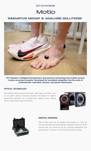
‘Innovative solutions
Open the catalog to page 1
• Founded 1998 - Researchers from nearby CEIT R&D center • Engineering firm with 20-24 engineers & sw dev on board
Open the catalog to page 2
Business Units
Open the catalog to page 3
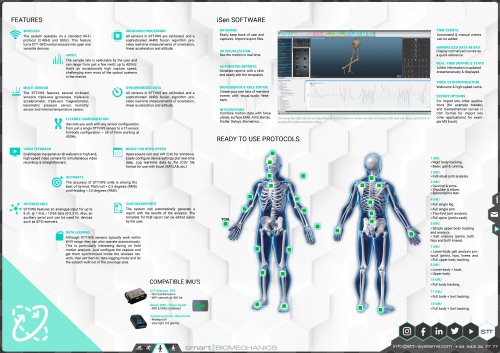
Inertial Video-based motion analysis systems Comprehensive solutions for full-body 3D motion analysis Flexible I MU configurations for full-body kinematic analysis
Open the catalog to page 5
the 3D optical motion analysis software
Open the catalog to page 6
ip Motio © STT Systems Overview 7
Open the catalog to page 7
UNIVERSITY OF APPLIED SCIENCES Harbor-UCLA FREMAP adidas BHBIKES.COM
Open the catalog to page 8
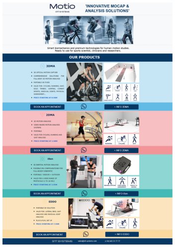
Gait analysis Sports Rehabilitation Cycling Golf & Tennis Research Clinical
Open the catalog to page 10
WHAT IS A PROTOCOL? The ease of use is one of the main goals of all 3DMA products. However, this should not be at odds with providing rich and meaningful data… So how is this balance achieved? In 3DMA, each analysis protocol is made up of 6 components that help conduct the analysis very efficiently.
Open the catalog to page 11
Bike fitting (FULL BODY & FLOOR) 20 3 Required Placed an anatomical Placed on the floor as The floor definition resulting from londmarbs as described described below a good calibration is enough Marker #16 (left foot) or #15 (right foot): With the crank positioned at 90° as instructed, this marker is fixed on the boot, vertically aligned with the pedal axle and at the same height as marker #14. Once more with the cyclist on the bike (hands on the handlebar, in pedaling posture), place the markers on the spine: Locate the upper edge of Sacrum. On L1-L2 (first or second Lumbar vertebrae). On T6-T7...
Open the catalog to page 12
Automatic Labelling Instant Metrics Meaningful graphs Final Report
Open the catalog to page 13
Automatic Labelling Instant Metrics Meaningful graphs Final Report
Open the catalog to page 14
□ OBUIgllQ Select Open Hew Save Import Export Close Edit user capture capture capture ' parameters Cycling and Bike Fitting, Samples Joe Cooper -6 cameras 100FPS Clear Create events event Stride Normative Create Create report multi-report Analysis nm 9 Sports ^ Gait © Rehab SIT InSight licenses Average Right FEET & ANKLES Foot Rotation Ankle Flexion Ankle Flexion Crank @0° Ankle Flexion Crank @90° Ankle Flexion Crank @180® Ankle Flexion Crank @270° Crank @ Max Ankle Extension Crank @ Max Ankle Flexion Ankle to GT Lateral Oscillation Knee Flexion Knee Lateral Oscillation Knee to M5 Lateral Oscillation...
Open the catalog to page 15
user capture capture capture data dataT Metrics Dashboard OVERVIEW PARAMETERS Cadence Stride length Step length Ground contact time Swing time UPPER BODY Trunk Tit - Anterior/Posterior (+/-) Trunk Obliquity - Right/Left (+/-) Shoulders-Hips Rot - Right/Left [+/-) PELVIS Tit - Anterior/Posterior (+/-) Obliquity - Right/Left (+/-) Rotation - Int/Ext (+/-) Flexion/Extension (+/-) Valgus/Varus {+/-) Intemal/External Rotation (+/-) ANKLES Left Dorsal/Plantar Flexion (+/-) Inversion/Eversion {+/-) Intemal/External Rotation (+/-)
Open the catalog to page 16
Backswing time Downswing time Total swing time Time Impact/Max acc. Time Impact/Min acc. JOINTANGLES Knee flexion Hip line side bend Shoulder line side bend Hip-Shoulder-Wrist Elbow flexion Wrist set angle Knee flexion Hip line side bend Shoulder line side bend Wrist set angle Arm-shoulder abduction Club to ankles TURN Ankle line Knee line Hip line Shoulder line TURN VS. TARGET LINE Ankle line Knee line Hip line Shoulder line DIRECT DISTANCES COG to ball Grip to ball Grip to head COG to grip Grip to head COG to grip CLUB VALUES Club angle to ground Club angle to target line Ankle line Knee line...
Open the catalog to page 17
Average Right Ankle to GT Lateral Oscillation mm 13 23 25 Knee Flexion Knee Lateral Oscillation mm Knee to M5 Lateral Oscillation mm 24 41 42 Knee to GT Lateral Oscillation * ' ‘ ’ □ R fjlil A- < e </x CrH'K l~~l sft Knee vs Crank B-D Cadence E~d Feet and ankle angles Ed Ankle distances B-0 Knee angles 0 Left knee flexion 0 Right knee flexion E- □ Knee distances E-d Knee front trajectories E-O Thigh angles E~d Hip and pelvis angles E □ Hip and pelvis distances E d Trunk angles Ed T runk distances E-d Back points _
Open the catalog to page 18
InstantMetrics OVERVIEW Crank Angle FEET & ANKLES Foot Rotation Foot Angle to Horizontal Ankle Flexion Ankle Flexion Crank @0° Ankle Flexion Crank @90° ° Ankle Flexion Crank @180° “ Ankle Flexion Crank @270° ° Crank @ Max Ankle Extension “ Crank @ Max Ankle Flexion “ Ankle to GT Lateral Oscillation mm Knee Lateral Oscillation mm Average Right Knee to M5 Lateral Oscillation mm Knee to GT Lateral Oscillation mm HIPS Hip Flexion Hip Height Difference Hip Vertical Oscillation GT-M5 Lateral Distance Hip Setback Pelvis Rotation Pelvis Fore-Aft Swing Pelvis Vertical Swing Hip to Shoulder Tilt Knee-Hip-Shoutder...
Open the catalog to page 19
InstantMetrics Meaningful graphs FinalReport Configuration capture sequence l&l'ff _DEMO SAMPLES, Load Close reference reference Create Auto Edit Normative data Rules Activate Display values Samples: 73 Gender: Unknown Footwear: Unknown Age: Left strides Double dick on a curve to delete it.
Open the catalog to page 20
Bike fitting (body & floor) Lower Limb Kinematics - Knees
Open the catalog to page 21
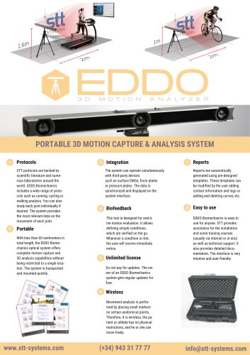
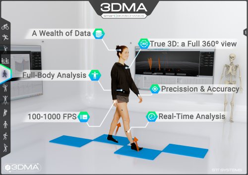
REAL-TIME Data sets are presented live and automatically: Parameters, graphs and 3D views. Get immediate feedback for any dynamic adjustment of the bike. FULL-BODY After a few seconds, 3DMA provides tracking data and automatic analysis of the entire body: yes, on every joint. TRUE 3D Motion capture cameras track markers in 3D space which are used to reconstruct the actual body motion. Use pan, tilt and zoom tools to move around at will. 100-1000 FPS The data is acquired, processed and displayed to the user at a frame rate of at least 100 Hz/FPS (Frames Per Sec
Open the catalog to page 22
• PRECISION & ACCURACY A well-calibrated system boasts millimetric precision and accuracy in marker tracking. Seamlessly detect 1 -2 mm marker shifts anywhere in the 'capture volume’! • AUTOMATIC EVENTS DETECTION Example: in gait analysis, automatic detection of initial contact and take off. • HIGH SPEED VIDEO INTEGRATION Integrate high-speed video cameras together with the 3D reObation. Possibility of defining rules to check certain conditions in real time. The system informs the user when these conditions are met during recording. O
Open the catalog to page 23All STT Systems catalogs and technical brochures
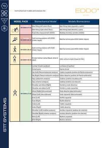 EDDO MODELS
1 Page
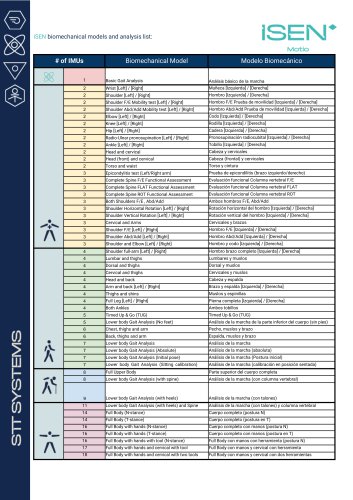 ISEN MODELS
1 Page
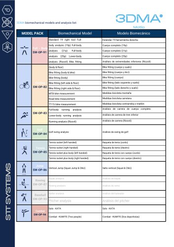 3DMA MODELS
2 Pages
 Medical Sector Products
3 Pages
 Products
1 Page
 EDDO
EDDO1 Page
 2DMA
2DMA2 Pages
 iSen
iSen1 Page
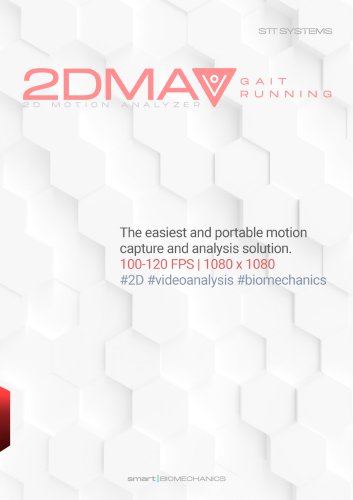 2DMA GAIT RUNNING
2 Pages
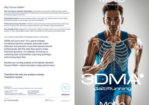
 3DMA
3DMA2 Pages
 GAIT & RUNNING 3DMA
2 Pages
 CYCLING 3DMA
2 Pages