
- Catalogs
- SuperHandy
- SuperHandy Electric Trailer Dolly Pro

SuperHandy Electric Trailer Dolly Pro
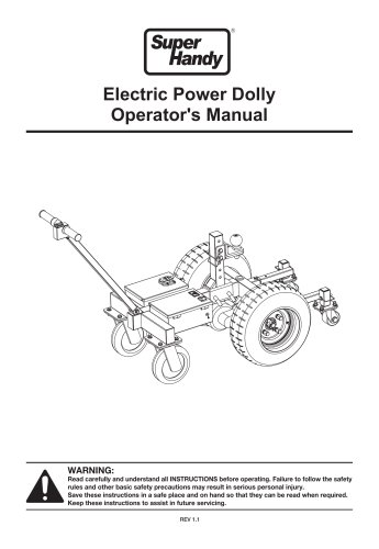
SuperHandy Electric Trailer Dolly Pro
Warning
Before using the Electric Power Dolly, read and understand all instructions to prevent serious injury. Use only on level paved surfaces with less than a 4° grade. It is not a substitute for a vehicle. Follow safety precautions, including proper battery handling and disposal, using manufacturer-approved components, and avoiding operation under the influence of substances.
Technical Specifications
The Superhandy Electric Power Dolly is designed for towing trailers and RVs over short distances. It features a DC24V, 9Ah power supply, 800W power, and a maximum trailer weight capacity of 7500lbs.
Main Components
Key components include a start switch, transformer, controller, power wheel, hitch ball, and batteries. It has a 7-core socket for power supply and a voltage and battery level indicator.
Assembly
Assembly involves installing the handlebar, connecting connectors, and assembling the hitch ball adjusting stem and rear support. Ensure proper alignment and secure fastening.
Operation
Before operation, ensure all components are secure, tires are in good condition, and the battery is charged. Test the dolly without load to ensure functionality. Adjust the hitch ball position for traction and stability.
Service Guide
Includes instructions for replacing the start switch, power wheels, controller, power switch, and batteries. Conduct maintenance under professional guidance and dispose of damaged components according to environmental regulations.
Maintenance and Storage
Store in a cool, dry, and dust-free environment. Avoid rough handling during transportation.
Warranty
A twelve-month warranty covers workmanship, excluding wearing parts. The warranty starts from the purchase date and covers material quality and workmanship only. Improper usage or modifications void the warranty.
Troubleshooting
- Problem: Power dolly does not work.
Possible Causes: Power shut down.
Corrective Actions: Check battery status, ensure the power switch is 'on', and secure connection cable. - Problem: Power dolly stops during operation.
Possible Causes: Low batteries or overload.
Corrective Actions: Recharge fully and reduce load weight.
Exploded and Parts List
Includes a detailed parts list with part numbers, descriptions, and quantities. Quick-wear parts are marked with an asterisk (*).
Contact Information
For support, contact Great Circle USA at 1-866-493-0524 or [email protected]. More information is available at www.greatcircleus.com.
Catalog excerpts
Electric Power Dolly Operator's Manual Read carefully and understand all INSTRUCTIONS before operating. Failure to follow the safety rules and other basic safety precautions may result in serious personal injury. Save these instructions in a safe place and on hand so that they can be read when required. Keep these instructions to assist in future servicing. REV 1.1
Open the catalog to page 1
DO NOT USE THIS PRODUCT TO MOVE TRAILER LOADED OR UNLOADED ACROSS ANYTHING OTHER THAN LEVEL PAVED SURFACES WITH LESS THAN A 4° GRADE. DO NOT ATTEMPT TO USE THIS PRODUCT ON A BOAT LAUNCH. THIS PRODUCT IS NOT INTENDED TO REPLACE YOUR VEHICLE. • Thoroughly review the "Installation and Operation Guidelines" and familiarize yourself with your electric dolly and its operation. • Never store the battery pack together with nails, screws, keys and other metallic or sharp objects. These items may cause short circuit of the battery terminal resulting in damage to the battery and may cause a fire, endangering...
Open the catalog to page 3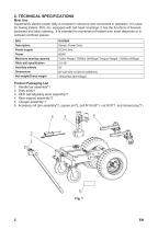
Superhandy electric power dolly is compact in structure and convenient in operation. It is used for towing trailers, RVs, etc. equipped with ball head couplings. It has the functions of forward, backward and basic steering. It is intended for movement of trailers over short distances or in compact confined spaces. Product Packaging List 3. Hitch ball adjusting stem assembly*1 6. Accessory kit (pin assembly*2, square pin*2, bolt M10*55*1, nut M10*1, and domed plug*1)
Open the catalog to page 4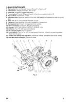
1. Start switch: Control the dolly to move "forward" or "backward" 2. Transformer: Voltage conversion, 24V to 12V 3. Controller: A device to preset instructions 4. 7-core socket: Provide 12V power supply to the electromagnetic brake or lift 5. Power wheel: Transmit the traction 6. Adjusting stem: Adjust the position of the hitch ball forward and backward as well as up and down 7. Hitch ball: To be connected with the trailer coupler 8. Frame nut: Used when the hitch ball is installed in a low position 9. Rear support bar: Prevent the equipment from cocking 10. Universal wheel: Control the direction...
Open the catalog to page 5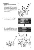
4. ASSEMBLY 1. Installation of the handle bar assembly (See Fig.3) Open the lid of the control box, thread the handle assembly lead through the square opening at the front of the frame (Step 1) and lead it out through the large round hole on the side of the control box (Step 2). Insert the handle bar (Step 3), align with the holes and insert the bolts M10x55 (Step 4), and tighten the M10 nuts (Step 5). 2. Connection of connectors (See Fig.4) Connect the handle bar leads to the corresponding 2P and 3P connectors. Fig. 4 3. Installation of the hitch ball adjusting stem assembly (See Fig.5) Align...
Open the catalog to page 6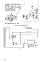
4. Installation of the rear support assembly (See Fig.6) Insert the two rear support assemblies into the square holes of the frame respectively (Step 1), align the holes at the right positions and insert the 8×60 square pins for fixation (Step 2). 5. Battery cable connection (See Fig.7) Electrical Schematic Diagram Power display Operating switch Power switch Seven core socket Holzer line Controller
Open the catalog to page 7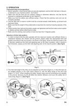
5. OPERATION Commissioning and preparations 1. Before operation, check that all bolts are securely tightened, and the hitch ball stem is Securely fastened to your desired position and locked. 2. Make sure that the tires are not cracked, bulging or otherwise defective, and that the tire pressure is maintained at 60±2psi (4.2±0.1kgs/cm²). 3. Make sure that the battery has sufficient power. Check that the switches work and can be smoothly operated. 4. Test the dolly with no load to confirm that the universal wheels rotate flexibly, go forward and backward freely. 5. Make sure that the weight of...
Open the catalog to page 8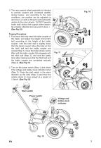
3. The rear support wheel assembly is intended to provide support and increased stability during towing., and according to the road conditions, can position can be adjusted up and down as well as forward and backwards relative to the main wheels. DO NOT operate trailer dolly without the support wheel assembly properly attached and secured in place. i. (See Fig.10) Towing Procedure 1. First move the dolly near the trailer coupler of the trailer, and adjust the height of the hitch ball according to the height of the trailer coupler, until the hitch ball is slightly lower than the trailer coupler....
Open the catalog to page 9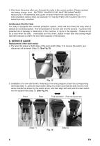
3. Shut down the power after use. And park the dolly in the correct position. Please maintain the battery charge level. BATTERY CHARGE LEVEL MUST BE MAINITAINED REGUALRLY OTHERWISE THE LEAD ACID BATTERY MAY BECOME FULLY DISCHARGED, RESULTING IN DAMAGE TO THE BATTERY OR FAILRE FOR IT TO MAINTAIN ANY CHARGE. OVERLOAD PROTECTION The dolly is equipped with overload protection system, which will shut down the dolly when it detects an overload situation. This will protection is for both user and the product. To prevent the potential risk of damage or destruction of the machine, or injury to the operator.....
Open the catalog to page 10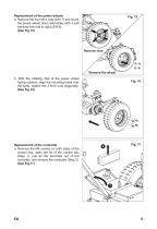
Replacement of the power wheels a. Remove the four M14 nuts (S/N 7) and knock the power wheel down alternately with a soft hammer from left to right (S/N 8). (See Fig.15) Remove nuts Remove the wheel b. With the inflating inlet of the power wheel facing outward, align the mounting holes over the bolts, tighten the 4 M14 nuts diagonally. (See Fig.16) Replacement of the controller a. Remove the M4 screws on both sides of the control box, open the lid of the control box (Step 1), pull all the terminals out of the controller, and remove the controller (Step 2). (See Fig.17)
Open the catalog to page 11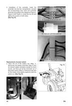
b. Installation of the controller. Insert the controller into the box compartment, connect the corresponding color wires and controller terminals according to the diagrams (Figure a, Figure b and Figure c), close the box lid and tighten the screws on both sides. (See Fig.18) (a) Connect with the rear axle (b) Connect with the batteries (c) Connect with the start switch Replacement of power switch a. Open the lid of the battery box (Step 1), disconnect the battery terminals (Step 2) first (to prevent safety accidents caused by short circuit), and then pull all the terminals out of the power switch...
Open the catalog to page 12All SuperHandy catalogs and technical brochures
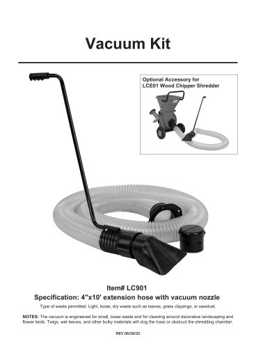 Vacuum Kit
2 Pages
 SuperHandy Electric Snow Thrower
12 Pages
 SuperHandy Electric Mini Chainsaw
12 Pages
 SuperHandy Wood Chipper Mini
13 Pages
 Superhandy Bath Lift Cushion
2 Pages
 Superhandy Mobility Scooter
9 Pages
 Passport Flex
2 Pages







- Wheelchair
- Outdoor wheelchair
- Indoor wheelchair
- Wheelchair with legrest
- Folding wheelchair
- Black wheelchair
- Patient lifter
- Electric wheelchair
- Electric patient lift
- Mobility scooter
- Electric mobility scooter
- Aluminium frame wheelchair
- Seat cushion
- Patient lift on casters
- Lifting patient lift
- 4-wheel mobility scooter
- Washable pad
- Anatomical pad
- Wheelchair with armrests
- Mobility scooter with basket