- Catalogs
- SUTO iTEC GmbH
- S211 / S215 / S220
S211 / S215 / S220
1 /25Pages

S211 / S215 / S220
1 /25Pages
Catalog excerpts

Instruction and operation manual
Open the catalog to page 1
Dear Customer, Thank you for choosing our product. The operating instructions must be read in full and carefully observed before starting up the device. The manufacturer cannot be held liable for any damage which occurs as a result of non-observance or noncompliance with this manual. Should the device be tampered with in any manner other than a procedure which is described and specified in the manual, the warranty is cancelled and the manufacturer is exempt from liability. The device is destined exclusively for the described application. SUTO offers no guarantee for the suitability for any other...
Open the catalog to page 2
1 Safety instructions Please check if this instruction manual matches with the product type. Please observe all notes and instructions indicated in this manual. It contains essential information which must be observed before and during installation, operation and maintenance. Therefore this instruction manual must be read carefully by the technician as well as by the responsible user or qualified personnel. This instruction manual must be available at the operation site of the dew point sensor at any time. In case of any obscurities or questions, regarding this manual or the product, please contact...
Open the catalog to page 4
ATTENTION! Permitted operating parameters! Observe the permitted operating parameters, any operation exceeding this parameters can lead to malfunctions and may lead to damage on the instrument or the system. • Do not exceed the permitted operating parameters. Make sure the product is operated in its permitted limitations. Do not exceed or undercut the permitted storage and operation temperature and pressure. General safety instructions • It is not allowed to use the product in explosive areas. Please observe the national regulations before/during installation and operation. It is not allowed...
Open the catalog to page 5
2 Registered trademarks SUTO® Registered trademark of SUTO iTEC MODBUS® Registered trademark of the Modbus Organization, Hopkinton, USA HART® Registered trademark of the HART Communication Foundation, Austin, USA PROFIBUS® Registered trademark of the PROFIBUS User Organization, Karlsruhe, Germany
Open the catalog to page 6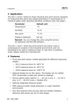
3 Application The S211 / S215 / S220 are three industrial dew point sensors designed for measuring dew point and related parameters in compressed air or industrial gases under specified operating conditions (See next page ). Parameter Default unit Pressure (optional) Remark: You can change the units using the service kit (optional) and the SFA software. The S211 / S215 / S220 dew point sensors are mainly used in compressed air systems in the industrial environment, and not developed to be used in explosive areas. To use them in explosive areas, please contact the manufacturer. Three dew point...
Open the catalog to page 7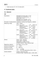
High accuracy of ± 2°C Td dew point. 5 Technical data 5.1 General Standard unit dew point: °C Td Standard unit temperature: °C other units: °F, K Standard unit humidity: % rH Standard unit pressure: bar (g) Principle of measurement Capacitive method and frequency method Measuring range S215 Dew point Relative Humidity Temperature Pressure (option) S211 Dew point Relative Humidity Temperature Pressure (option) S220 Dew point Relative Humidity Temperature Pressure (option) S215 / S211: Polymer S220: QCM + Polymer Temperature sensor: Pt100 Pressure sensor: Piezo resistive type Measuring medium Ambient...
Open the catalog to page 8
304) Display cover: PC + ABS Protection class Display (optional) 0.66” OLED display for displaying the measured value and unit 340° horizontally rotatable** See dimensional drawing on the page 11 Screwing thread * For CO2, the measurement range of S211 is limited to -40°C Td ** The rotation force cannot exceed 3.0 N.m 5.2 Electrical data Power supply Current consumption 5.3 Output signals Analog output Analog output scaling Modbus output Modbus communication Mode: RTU Baud rate: 19200 Device address: last 2 digits of serial number Farming / parity / stop bit: 8 / N / 1
Open the catalog to page 9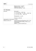
Response time: 1 second Response delay: 0 ms Interframe spacing: 7 char Dew point: +/- 1 °C Td (0 ... 20°C Td) +/- 2 °C Td (-60 ... 0 / +20 ... +50°C Td) +/- 3 °C Td (-100 ... -60°C Td) Temperature: ± 0.3°C Pressure: 0.5% FS Repeatability of dew point ± 0.5°C Stated accuracy at Ambient/process temperature 23°C ± 3°C Ambient/process humidity <95% rH, no condensation Airflow > 2 l/min at sensor tip
Open the catalog to page 10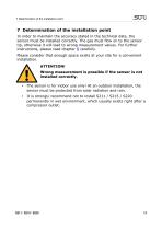
7 Determination of the installation point 7 Determination of the installation point In order to maintain the accuracy stated in the technical data, the sensor must be installed correctly. The gas must flow on to the sensor tip, otherwise it will lead to wrong measurement values. For further instructions, please read chapter 8 carefully. Please consider that enough space exists at your site for a convenient installation. ATTENTION! Wrong measurement is possible if the sensor is not installed correctly. • The sensor is for indoor use only! At an outdoor installation, the sensor must be protected...
Open the catalog to page 13
8 Installation Before installing the sensor, please make sure that all components listed below are included in your package. Qty Description Item no. (Model dependent) Depending on orders: Plug: C219 0059 M12 plug or M12 cable Cable: A553 0104/A553 0105 Instruction manual Calibration certificate Remark: The item number of the model varies depending on the chosen measurement range and signal output. 8.1 Installation requirements The flowing air or gas must pass the sensor tip for a proper measurement. This can be realized with a measurement chamber. For an installation without the measuring chamber,...
Open the catalog to page 14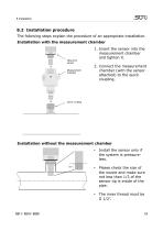
8.2 Installation procedure The following steps explain the procedure of an appropriate installation. Installation with the measurement chamber 1. Insert the sensor into the measurement chamber and tighten it. 2. Connect the measurement chamber (with the sensor attached) to the quick coupling. Installation without the measurement chamber • Please check the size of the nozzle and make sure not less than 1/3 of the sensor tip is inside of the pipe. Install the sensor only if the system is pressureless. The inner thread must be G 1/2”
Open the catalog to page 15All SUTO iTEC GmbH catalogs and technical brochures
 S520
S5204 Pages
 S415
S4154 Pages
 S421
S42144 Pages
 Product guide 2020/2021
104 Pages
- Medical sensor
- Laboratory testing system
- Laboratory software
- Windows software
- Monitoring sensor
- Monitoring software
- Medical gas flow meter
- Hospital flow meter
- Control analyser
- Measurement software
- Analyser for the pharmaceutical industry
- Gas sensor
- Temperature testing system
- O2 flow meter
- USB data-logger
- Recording software
- O2 analyzer
- Server software