S421
1 /44Pages

S421
1 /44Pages
Catalog excerpts

Instruction and operation manual S421 Thermal mass flow sensor
Open the catalog to page 1
Dear Customer, Thank you for choosing our product. Please read this manual in full and carefully observe the operating instructions before starting up the device. The manufacturer cannot be held liable for any damage which occurs as a result of non-observance or non-compliance with this manual. Should the device be tampered with in any manner other than a procedure which is described and specified in the manual, the warranty is void and the manufacturer is exempt from liability. The device is designed exclusively for the described application. SUTO offers no guarantee for suitability for any...
Open the catalog to page 2
1 Safety instructions Please check if this instruction manual matches the product type. Please observe all notes and instructions indicated in this manual. It contains essential information which must be observed before and during installation, operation, and maintenance. Therefore this instruction manual must be read carefully by the technician as well as by the responsible user / qualified personnel. This instruction manual must be available at the operation site of the flow sensor at any time. In case of any obscurities or questions, regarding this manual or the product, please contact the...
Open the catalog to page 4
ATTENTION! Permitted operating parameters! Observe the permitted operating parameters. Any operation exceeding these parameters can lead to malfunctions and might lead to damage on the instrument or the system. • Do not exceed the permitted operating parameters. Make sure the product is operated in its permitted limitations. Do not exceed or undercut the permitted storage and operating temperature and pressure. The product should be maintained and calibrated frequently, at least annually. General safety instructions • It is not allowed to use the product in explosive areas. Please observe the...
Open the catalog to page 5
Make sure that the transportation temperature of the sensor without the display is between -30 ... +70°C and with the display between -10 ... +60°C. For storage and transportation, it is recommended to use the packaging which comes with the sensor. Please make sure that the storage temperature of the sensor is between -10 ... +50°C. Avoid direct UV and solar radiation during storage. For the storage, the humidity must be <90% with no condensation. 2 Registered trademarks SUTO® Registered trademark of SUTO iTEC MODBUS® Registered trademark of the Modbus Organization, Hopkinton, USA HART® Registered...
Open the catalog to page 6
3 RF exposure information and statement 3 RF exposure information and statement This equipment complies with FCC RF radiation exposure limits set forth for an uncontrolled environment. This equipment should be installed and operated with a minimum distance of 20 cm between the radiator and your body. This device complies with part 15 of the FCC rules. Operation is subject to the following two conditions: (1) this device might not cause harmful interference, and (2) this device must accept any interference received, including interference that might cause undesired operation. Remark: The manufacturer...
Open the catalog to page 7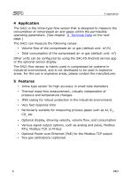
4 Application The S421 is the inline-type flow sensor that is designed to measure the consumption of compressed air and gases within the permissible operating parameters. (See chapter 6 Technical Data on the next page.) The S421 can measure the following values: • Volume flow of the compressed air or gas (default unit: m3/h) Total consumption of the compressed air or gas (default unit: m3) Other units can be configured by using the S4C-FS Android service app or the optional sensor display. The S421 flow sensor is mainly used in compressed air systems in industrial environment, and is not developed...
Open the catalog to page 8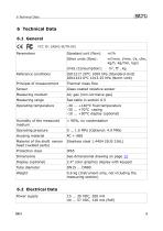
6 Technical Data 6.1 General FCC ID: 2ASK2-SUTO-001 Standard unit (flow): Other units (flow): Units (Consumption): Reference conditions Thermal mass flow Glass-coated resistive sensor Measuring medium Measuring range Operating temperature Humidity of the measured medium Operating pressure Housing material Material of the shaft sensor head (welded parts) Protection class See dimensional drawing on page 12 Display (optional) 2.4” color graphics display with keypad Tube diameter 0.6 kg (Instrument only, not including the measuring section) 6.2 Electrical Data Power supply
Open the catalog to page 9
6.3 Output-Signals Analogue output Signal: 4 ... 20 mA, isolated Scaling: 0 to max flow Max load: 250R Pulse output 1 pulse per consumption unit, isolated switch, max. 30 VDC, 200 mA (pulse length: 10 ... 120 ms, depends on flow rate) Modbus output M-bus output ± (1.5% of reading + 0.3% FS) (optional 1% of reading) Temperature drift: < 0.05%/K Ambient/process temperature 23°C ± 3°C Ambient/process humidity <90% Process pressure at 0.6 MPa *Specified accuracy is valid only within the minimum and maximum flow rates that are indicated in section 6.5 on this page. 6.5 Volumetric flow ranges Inch
Open the catalog to page 10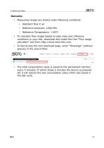
Measuring ranges are stated under following conditions: • To fast access the tool download page, enter "flowrange" (without spaces) in the search field. To calculate flow ranges based on pipe sizes and reference conditions in your site, download and install the free "Flow range calculator" tool from http://www.suto-itec.com. The total consumption value is saved to the permanent memory every 5 minutes. If within these 5 minutes the device is powered off, it will restore the last consumption value which was saved in the l
Open the catalog to page 11
H1 from pipe R center to External casing top thread [mm] Pipe nominal size inch(DN)
Open the catalog to page 12
H1 Flange (EN 1092-1 from PN40) Pipe L L1 H pipe nominal total inlet total center to size length length height ØD ØK n x ØL casing inch(DN) [mm] [mm] [mm] (mm) (mm) (mm) top [mm]
Open the catalog to page 13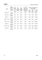
Pipe L L1 H nominal total inlet total size lengt length height inch(DN h [mm] [mm] ) [mm] H1 Flange (ANSI/B16.5 from pipe class 300) center to casing top ØD ØK n x ØL [mm] (mm) (mm) (mm)
Open the catalog to page 14
8 Determining the installation point 8 Determining the installation point To maintain the accuracy stated in the technical data, the sensor must be installed inline and fitted to tubes with the same diameter. Please make sure that it has unhindered flow characteristics. Unhindered flow characteristics are achieved if the section in front of the sensor (inlet) and behind the sensor (outlet) is sufficiently long, absolutely straight, and free of obstructions such as edges, seams, curves etc.. Please consider that enough space exists at your site for an adequate installation as described in this...
Open the catalog to page 15All SUTO iTEC GmbH catalogs and technical brochures
 S520
S5204 Pages
 S211 / S215 / S220
25 Pages
 S415
S4154 Pages
 Product guide 2020/2021
104 Pages
- Medical sensor
- Laboratory testing system
- Laboratory software
- Windows software
- Temperature sensor
- Monitoring sensor
- Monitoring software
- Medical gas flow meter
- Hospital flow meter
- Control analyser
- Measurement software
- Analyser for the pharmaceutical industry
- Gas sensor
- Temperature testing system
- O2 flow meter
- USB data-logger
- Recording software
- O2 analyzer
- Pressure sensor
- Server software