- Catalogs
- Systemair HSK
- AQWL/AQWH/AQWR 1404 to 2406
AQWL/AQWH/AQWR 1404 to 2406

AQWL/AQWH/AQWR 1404 to 2406
The document details the specifications for AQWL/AQWH/AQWR air-cooled water chillers, available in cooling only, heat pump, and total heat recovery versions. These units are designed with a slim and light structure, optimized for container transport, and feature symmetric refrigerant circuit configurations to reduce pressure drops. Standard coils are arranged in V configurations for better air distribution, and the units boast high energy efficiency with EER values over 2.9 and COP values over 3.2.
The chillers include bi-flow electronic expansion devices, optimized coil designs, and high power hermetic scroll compressors. Special versions like HSE (High Seasonal Efficiency) and HT (High Temperature) offer enhanced performance with ESEER values over 4.5. The units are equipped with hydro kits, safety valves, and are available in various acoustic options (BLN, LN, ELN).
The AQWL/AQWH units operate with HFC 410A refrigerant and are available in five sizes, with capacities ranging from 380 to 702 kW. They feature hermetic scroll compressors, electronic expansion valves, and dual circuit plate heat exchangers. The units are designed for low noise emissions and are available in standard, high seasonal efficiency, high temperature, and high pressure fan versions.
The cabinet is made of galvanized steel with a polyester powder-based painting for corrosion protection. The structure is fastened with non-corrosive screws and bolts.
Each unit has two independent refrigerant circuits with hermetic scroll compressors, liquid line and discharge line shut-off valves, and electronic expansion valves. Heat pump units include 4-way reversing valves and liquid receivers.
The units are equipped with 4 or 6 hermetic scroll compressors per circuit, featuring electronic control devices for protection against overheating and overloading.
The evaporator is a dual circuit brazed stainless steel plate type heat exchanger, insulated to prevent freezing.
Condenser coils are made of copper tubes with aluminum fins. Fans are large diameter, direct drive axial type, with special inverter fans used in certain versions.
Fan speed is controlled to operate at low ambient temperatures, with step type control for BLN and LN versions and stepless control for ELN versions.
The electrical board is protected by a metal case with IP54 rating. The units feature a microprocessor-based control system for managing compressors, temperature regulation, and alarms.
Safety devices include a power disconnect switch, HP switches, and antifreeze temperature sensors. Control devices include HP and LP transducers and various temperature sensors.
The units comply with Machine Directive 2006/42/EC, Low Voltage Directive 2006/95/EC, Electromagnetic Compatibility Directive 2004/108/EC, and Pressure Equipment Directive 97/23/EC.
Hydro kits are available on board or remotely, with options for buffer tanks and various components like pumps, expansion tanks, and safety valves.
This document provides technical specifications and options for AQWL/AQWH units in the ELN version, focusing on factory-installed options, field-installed accessories, refrigerant flow diagrams, operating limits, correction factors, and physical data.
The hydro kit is specifically for AQWL/AQWH units and includes various protocol kits for BMS (ModBus, Lonwork, Bacnet, WEBctrl), Ethernet TCP/IP interface, compressors soft starter, fan speed controller for low ambient operation, power factor correction capacitors, compressors overload protection, GSM, manometers, condenser coil treatments, high static pressure fans, coil guards, chiller grilles, compressor jacket, water pump acoustic box, total heat recovery, desuperheater, and onboard hydro kits with or without buffer tanks.
These include remote ON/OFF control, remote keyboard panel, master and slave control for up to 4 units, chiller grilles, spring anti-vibration mounts, flow switch, pressure switch, water filter, and remote hydro kits with buffer tanks and pumps.
Detailed diagrams for AQWL, AQWH, and AQWR units are provided, showing components like compressors, condensers, filter driers, expansion valves, heat exchangers, and safety/control devices such as pressure switches and temperature sensors.
Specifications for AQWL and AQWH units include minimum and maximum flow rates, pressure drops, ambient air temperature ranges, external static pressure, recommended system chilled water volume, and power supply voltage. The document also provides graphical data on leaving water temperature versus ambient temperature for different models and configurations.
Includes fouling factors for evaporators and condensers, altitude factors affecting cooling capacity and power input, and system water volume calculations based on compressor running time and capacity steps.
Detailed specifications for AQWL STD/HSE/HPF - BLN and LN versions, including nominal cooling capacity, input power, energy efficiency ratings, number of refrigerant circuits, compressor details, evaporator and condenser specifications, fan details, weight, sound levels, and dimensions.
Data is based on specific conditions such as 7°C leaving chilled water temperature and 35°C condenser air temperature. Sound levels are measured according to ISO standard 3744 and Eurovent 8/1.
Details on power input, current, and start-up current for compressors at 400 V / 3 Ph / 50 Hz. Fan configurations include standard and electronic brushless fans with varying power and current specifications.
High-efficiency units (HSE) with inverter fans are available. Options for desuperheater versions and additional weights for configurations with pumps and tanks.
The document provides detailed specifications for various AQWL/AQWH models (1404, 1604, 1806, 2106, 2406) including maximum power input, maximum current input, and start-up current for different model versions (BLN, LN, ELN, HSE/HT/HPF). The units operate at 400 V / 3 Ph / 50 Hz.
Electrical data for AQWL/AQWH models using R410A refrigerant is provided, specifying power and current inputs for different models and versions. The data is crucial for ensuring compatibility and safety in electrical installations.
Sound power and pressure levels are detailed for each model version, measured at various frequencies. This information is essential for assessing the noise impact of the units in different environments.
The document includes extensive tables showing cooling capacities and input power requirements at various leaving water temperatures (LWT) and condenser air entering temperatures. This data is segmented by model and version (BLN, LN, ELN, HT), providing insights into performance under different operational conditions.
Important notes clarify that power input data is specific to compressors and that sound pressure levels are measured according to ISO standard 3744.
- Understanding the power and current requirements is critical for installation and operation.
- Sound data helps in planning for noise management in installations.
- Cooling capacity data assists in selecting the appropriate model for specific environmental conditions.
The document provides detailed specifications for AQWH models, focusing on heating and cooling capacities. It includes data on leaving water temperature (LWT) and condenser air entering temperature, with cooling capacity and input power values for various models and conditions. The data is presented in tabular form, showing how performance varies with temperature changes.
Information on total heat recovery for AQWR models is provided, detailing cooling capacity, input power, and heat recovery across different outlet condenser water temperatures. Additionally, evaporator and condenser water pressure drop curves are included for AQWL/AQWH units, with specific flow rates and pressure drop values.
The document outlines the dimensions for AQWL/AQWH models 1404 to 2406, specifying water connection sizes and electrical supply details. Installation guidelines for single and multiple units are provided, emphasizing space requirements and wall arrangements to ensure proper airflow.
Circulating pump curves for both low and high head pumps are included, showing available static pressure against flow rates for different models. This section aids in understanding the pump performance under various operational conditions.
Notes clarify that power input data is for compressors only, and flow rates refer to one condenser. The document concludes with a disclaimer about potential product changes as part of ongoing improvements.
Catalog excerpts

AQWL/AQWH/AQWR 1404 to 2406 Air Cooled Water Chillers Cooling Only, Heat Pump and Total Heat Recovery Engineering Data Manual
Open the catalog to page 1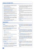
Features & Strength Points A more "slim and light" structure, while keeping the features of sturdiness (successfully performed at CESI laboratory, vibration tests in accordance with ASTM standards). Rivets as joints of the structural elements. Optimization of overall dimensions for container transport. Symmetric refrigerant circuit configuration to reduce the length of pipes and consequently the pressure drop in the circuit. Standard coils in Al/Cu, arranged in V configurations to get a better air distribution and then optimize its performance. Increasing the fin spacing to reduce...
Open the catalog to page 2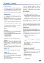
Specifications (continued) Cabinet and structure The unit cabinet and structure are made of heavy gauge galvanized steel. All the galvanized steel components are individually painted, with a polyester powder based painting (RAL 9001), under a special painting process before the assembly of the unit. This painting system performs and stands a homogeneous protection of the corrosion. All parts of the structure are totally fastened with non-corrosive screws and bolts. On high pressure fans of HPF units, the external static pressure (≤ 120 Pa) can be adjusted on site to match the customer demand...
Open the catalog to page 3
Specifications (continued) ➜ Remote signalling, by dry contacts : h) Circuit alarm unit ➜ Management of the hydro kit : start-up of pump, antifreeze heater of external tank. ➜ Management of the heat recovery mode by means of inlet water temperature sensor at the heat recovery condenser. The unit controller can also clearly show all control parameters of the machine on the liquid crystal display, such as : ➜ Display of superheating value. ➜ Display of the temperature at the evaporator inlet and outlet. ➜ Display of the ambient air temperature. ➜ Display of the circuit 1 and circuit 2 discharge...
Open the catalog to page 4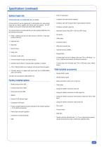
Specifications (continued) Optional hydro kits On board hydro kits and remote hydro kits are available. 3 Condenser coils with blue fins treatment. On board hydro kits can be supplied with or without buffer tank, while remote hydro kits are always supplied with internal tank and pump(s). The HPT models can be used as remote hydro kits for field installation. 3 Condenser coils with "Fin Guard Silver" (polyurethane) treatment. The on board hydro kit, located inside the unit, with or without buffer tank, has the following components : 3 High static pressure fans (ESP<120 Pa) for HPF version. ➜ Single...
Open the catalog to page 5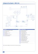
SAFETY / CONTROL DEVICES Note : For reasons of readability, one circuit only is shown. The second circuit is identical.
Open the catalog to page 6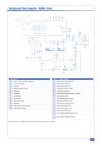
Note : For reasons of readability, one circuit only is shown. The second circuit is identical.
Open the catalog to page 7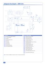
Note : For reasons of readability, one circuit only is shown. The second circuit is identical.
Open the catalog to page 8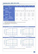
Operating Limits - AQWL 1404 to 2406 1404 Water outlet Brine outlet Liquid outlet temperature Chilled Liquid Maximum operating pressure Standard fans High pressure fans External static pressure Recommended system chilled water volume (2) Minimum capacity step Power supply voltage (4) Total unit flow rate and pressure are given for STD units. Caution : Minimum flow rates may only be used with brine solutions after reprogramming the unit parameters. Minimum water/brine volume of system (about 3 litres/kW). Max. ambient air temperature of +48 °C in part loaded conditions. Voltage : 400 V ± 10 %....
Open the catalog to page 9
Operating Limits - AQWL 1404 to 2406 (continued) 1404 - 1604 - 1806 - 2106 - 2406 ELN/HSE ELN Leaving water temperature (°C) Leaving water temperature (°C) Leaving water temperature (°C) (1) Water (2) Water and glycol (3) Water and FSC (4) Water, glycol and FSC (5) Reachable only with partialization. Leaving water temperature (°C
Open the catalog to page 10
Operating Limits - AQWH 1404 to 2406 1404 Maximum operating pressure Water outlet Standard fans High pressure fans External static pressure Recommended system chilled water volume (2) Minimum capacity step Power supply voltage (5) Brine outlet Heat pump Water outlet Liquid outlet temperature Chilled Liquid Total unit flow rate and pressure are given for STD units. Caution : Minimum flow rates may only be used with brine solutions after reprogramming the unit parameters. Minimum water/brine volume of system (about 3 litres/kW). Max. ambient air temperature of +48 °C in part loaded conditions....
Open the catalog to page 11
Operating Limits - AQWH 1404 to 2406 (continued) Cooling mode 1404 - 1604 - 1806 - 2106 - 2406 ELN/HSE ELN Leaving water temperature (°C) Leaving water temperature (°C) All units 25 20 Ambient temperature (°C) Leaving water temperature (°C) Heating mode Leaving water temperature (°C) Leaving water temperature (°C) (1) Water (2) Water and glycol (3) Water and FSC (4) Water, glycol and FSC (5) Reachable only with partialization.
Open the catalog to page 12
The minimum system water volume is calculated using the minimum compressor running time (1.5 minute for scroll compressor) and the lower capacity step (only one compressor running among the six compressors installed) : Water volume (litre) Unit total cooling capacity (W) Number of compressor steps Compressor minimum running time (minute) Evaporator temperature difference (°C) With t = 1.5 minute, AT = 5 °C and n = 6, the minimum system water volume is about V = 2.4 litres/kW.
Open the catalog to page 13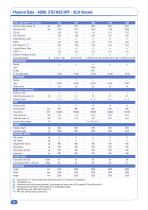
(1) Data based on 7 °C leaving chilled water temperature and 35 °C condenser air temperature. (3) Sound levels are at fully loaded conditions. Sound power level values refer to ISO standard 3744 and Eurovent 8/1. (4) Sound pressure levels refer to ISO standard 3744, parallelepiped shape. (*) High efficiency units (HSE) with inverter fans. (**) HPF units with high static pressure fans.
Open the catalog to page 14
(1) Data based on 7 °C leaving chilled water temperature and 35 °C condenser air temperature. (3) Sound levels are at fully loaded conditions. Sound power level values refer to ISO standard 3744 and Eurovent 8/1. (4) Sound pressure levels refer to ISO standard 3744, parallelepiped shape. (*) High efficiency units (HSE) with inverter fans.
Open the catalog to page 15All Systemair HSK catalogs and technical brochures
 VLS/VLH/VLR 524 to 1204 NEW
52 Pages
 Kälte- und Klimasysteme
208 Pages
 Fan Coil
16 Pages
 Water Source Heat Pump
8 Pages
 Heat Recovery Fresh Air Unit
8 Pages
 Axial Heating Unit
8 Pages
 High Pressure Fan Coil Units
8 Pages
 Blueline
8 Pages


Archived catalogs
 Fan Coil - 2014
8 Pages
 hsk
hsk72 Pages
 POOLLINE AIR HANDLING UNIT
4 Pages
 hygienline
8 Pages
 Flexine catalog
12 Pages
 CEILING TYPE
4 Pages
 MEDILINE PACKAGE HYGIENE
8 Pages
 blueline catalog
8 Pages
