
- Catalogs
- Systemair HSK
- VLS/VLH/VLR 524 to 1204 NEW


VLS/VLH/VLR 524 to 1204 NEW

VLS/VLH/VLR 524 to 1204 NEW
The VLS/VLH/VLR series of air-cooled water chillers are designed for cooling, heat pump, and total heat recovery applications. They use HFC 410A refrigerant and feature two independent refrigerant circuits with high-efficiency Scroll compressors. Available sizes range from 524 to 1204, with capacities from 137 to 336 kW.
The units include a "True Dual" two-circuit plate heat exchanger and V-shape coils with quiet fans. Acoustic options are Base Low Noise (BLN), Low Noise (LN), and Extra Low Noise (ELN). Versions include High Seasonal Efficiency (HSE), High Temperature (HT), and Special Inverter Fan (SIF).
Two options are available: Desuperheater (20% heat recovery) and VLR units (100% heat recovery).
Compliance with directives such as Machine Directive 2006/42/EC, Low Voltage Directive 2006/95/EC, Electromagnetic Compatibility Directive 2004/108/EC, and Pressure Equipment Directive 97/23/EC.
Features include R410A refrigerant, optimized coil design, bi-flow electronic expansion devices, and a new microprocessor. Hydro kits with or without buffer tanks and special valves for R410A are included.
The cabinet is made of galvanized steel with polyester powder coating. Compressors are hermetic scroll type, and the evaporator is a "Dual Circuit" brazed stainless steel plate type. Condenser coils are seamless copper tubes with aluminum fins.
Includes a power disconnect switch, HP switches, water differential pressure switch, antifreeze temperature sensor, and safety valve. The electronic control system manages compressor operation, water temperature regulation, and alarms.
Available with single or double pumps and buffer tanks, including components like expansion tanks, water filters, and safety valves.
ModBus protocol is available as a factory-installed option.
Details for VLS, VLH, and VLR units, including components like compressors, air-cooled condensers, and electronic expansion valves.
Temperature ranges, flow rates, ambient air temperature specifications, and system water volume calculations are provided.
Cooling capacities, efficiency ratings, sound levels, dimensions, and weights are specified for different models.
Sound levels measured according to ISO standard 3744 and Eurovent 8/1. Operating conditions based on specific temperature settings.
Consider cooling and heating capacity requirements, energy efficiency ratios, and sound level specifications for optimal performance and compliance.
Details on power input, current input, start-up current, power factor, and unit fuse size for various models.
Power input, current, and start-up current for compressors, and fan data including number, power, and current per fan.
Power cable dimensioning is the installer's responsibility, considering factors like rating, temperature, insulation, and line length.
Catalog excerpts

VLS/VLH/VLR 524 to 1204 NEW Air Cooled Water Chillers Cooling Only, Heat Pump and Total Heat Recovery Engineering Data Manual
Open the catalog to page 1
Key Points Units with R410A refrigerant (it will be the real replacement of R22). As near azeotropic mixture it behaves like a homogeneous substance (reduced service problems in case of leakage or re-charge) with negligible temperature glide. Special version (SIF) for high external static pressure (max. 120 Pa) with inverter fans (electronic brushless type motor). Axial fan Refrigerant with superior thermo-dynamical proprieties compared to R22 and R407C, it allows to have more efficiency or compact and lighter systems and larger operating limits (T ambient = -10 °C in heating mode). Modified...
Open the catalog to page 2
Specifications (continued) Cabinet and structure The unit cabinet and structure are made of heavy gauge galvanized steel coated with polyester powder based painting (RAL 9001). All parts of the structure are fastened totally with non-corrosive screws and bolts. Compressors Each unit is equipped with four compressors arranged in two tandems to suit the two refrigerant circuits. The compressors are of hermetic scroll type and fitted with an electronic control system ensuring protection against high temperature and excessive load. All compressors have direct-on-line starting and are mounted on rubber...
Open the catalog to page 3
^ Management of the electronic expansion valves by means of EXV controller allowing optimized functions: cooling, heating, start-up and defrost. ^ Management of external interlocks. ^ Management of the remote control: d) Unit power on/off e) Summary alarm signals ^ Remote signalling, by dry contacts: i) Alarm, circuit 2 ^ Management of the hydro kit: start-up of pump, antifreeze heater of external tank. ^ Management of the heat recovery mode by means of inlet water temperature sensor at the heat recovery condenser. The unit controller can also clearly show all control parameters of the machine on...
Open the catalog to page 4
- Safety valve, - Automatic air vent valve, - Thermal insulation for pipes and water pump(s), - Electrical box, - Antifreeze electric heater inside buffer tank (electric heater for pipes is not supplied). This hydro kit with 500 litres tank and above components, all located in a metallic cabinet, is fitted on the back of the unit; which implies an increase in unit length of about 900 mm. Factory installed options 3 ModBus protocol kit for BMS. 3 Lonwork protocol kit for BMS. 3 Bacnet protocol kit for BMS. 3 Compressors soft starter. 3 Pressure actuated stepless fan speed controller for low ambient...
Open the catalog to page 5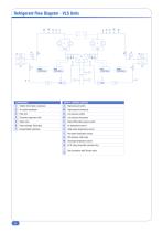
SAFETY / CONTROL DEVICES
Open the catalog to page 6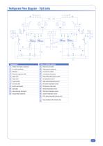
SAFETY / CONTROL DEVICES
Open the catalog to page 7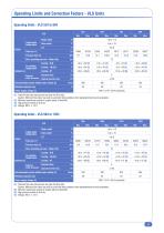
Air entering temperature Cooling - LN/ELN EXternal Standard fans static pressure special inverter fans Recommended system chilled water volume (2) Minimum capacity step Power supply voltage (4) (1) Total unit flow rate and pressure are given for BLN units. Caution: Minimum flow rates may only be used with brine solutions after reprogramming the unit parameters. (2) Minimum water/brine volume of system (about 3 litres/kW). (3) High pressure switch at 40.5 bar. Air entering temperature Cooling - LN/ELN EXternal Standard fans static pressure Special inverter fans Pa Pa Recommended system...
Open the catalog to page 9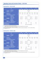
Water outlet Cooling - BLN Ambient ai Air entering temperature Cooling - LN/ELN EXternal Standard fans static pressure Special inverter fans Recommended system chilled water volume (2) Minimum capacity step Power supply voltage (4) (1) Total unit flow rate and pressure are given for BLN units. Caution: Minimum flow rates may only be used with brine solutions after reprogramming the unit parameters. (2) Minimum water/brine volume of system (about 3 litres/kW). (3) Max. leaving water temperature = 40 °C at -10 °C in fully loaded conditions and leaving water temperature = 45 °C in part loaded...
Open the catalog to page 10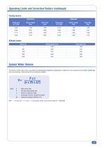
The minimum system water volume is calculated using the minimum compressor running time (1.5 minute for scroll compressor) and the lower capacity step (only one compressor running among the four compressors installed): Water volume (litre) Unit total cooling capacity (W) Number of compressor steps Compressor minimum running time (minute) Evaporator temperature difference (°C) With t = 1.5 minute, AT = 5 °C and n = 4, the minimum system water volume is about V = 3 litres/kW.
Open the catalog to page 11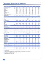
(1) Data based on 7 °C leaving chilled water temperature and 35 °C ambient air temperature. (3) Sound levels are at fully loaded conditions. Sound power level values refer to ISO standard 3744 and Eurovent 8/1. (4) Sound pressure levels refer to ISO standard 3744, parallelepiped shape. (*) High efficiency units (HSE) with inverter fans. (**) SIF units with high static pressure fans.
Open the catalog to page 12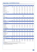
(1) Data based on 7 °C leaving chilled water temperature and 35 °C ambient air temperature. (3) Sound levels are at fully loaded conditions. Sound power level values refer to ISO standard 3744 and Eurovent 8/1. (4) Sound pressure levels refer to ISO standard 3744, parallelepiped shape. (*) High efficiency units (HSE) with inverter fans.
Open the catalog to page 13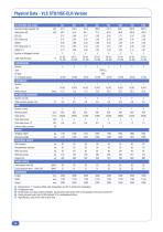
(1) Data based on 7 °C leaving chilled water temperature and 35 °C ambient air temperature. (3) Sound levels are at fully loaded conditions. Sound power level values refer to ISO standard 3744 and Eurovent 8/1. (4) Sound pressure levels refer to ISO standard 3744, parallelepiped shape. (*) High efficiency units (HSE) with inverter fans.
Open the catalog to page 14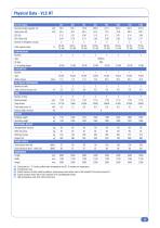
(1) Data based on 7 °C leaving chilled water temperature and 35 °C ambient air temperature. (3) Sound levels are at fully loaded conditions. Sound power level values refer to ISO standard 3744 and Eurovent 8/1. (4) Sound pressure levels refer to ISO standard 3744, parallelepiped shape. (*) High temperature units (HT) with inverter fans.
Open the catalog to page 15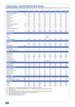
(1) Data based on 7 °C leaving chilled water temperature and 35 °C ambient air temperature. (2) Data based on 45 °C leaving hot water temperature and 7 °C ambient air temperature with 88 % relative humidity. (4) Sound levels are at fully loaded conditions. Sound power level values refer to ISO standard 3744 and Eurovent 8/1. (5) Sound pressure level values refer to ISO standard 3744, parallelepiped shape. (*) High efficiency units (HSE) with inverter fans. (**) SIF units with high static pressure fans.
Open the catalog to page 16All Systemair HSK catalogs and technical brochures
 Geniox Core brochure
18 Pages
 Geniox Catalogue
48 Pages
 Geniox VOClean
16 Pages
Archived catalogs
 Blueline
8 Pages
 High Pressure Fan Coil Units
8 Pages
 Axial Heating Unit
8 Pages
 Heat Recovery Fresh Air Unit
8 Pages
 Water Source Heat Pump
8 Pages
 Fan Coil
16 Pages
 Kälte- und Klimasysteme
208 Pages
 AQWL/AQWH/AQWR 1404 to 2406
48 Pages
 Fan Coil - 2014
8 Pages
 hsk
hsk72 Pages
 POOLLINE AIR HANDLING UNIT
4 Pages
 hygienline
8 Pages
 Flexine catalog
12 Pages
 CEILING TYPE
4 Pages
 MEDILINE PACKAGE HYGIENE
8 Pages
 blueline catalog
8 Pages


