Humerus IM Nail
1 /24Pages

Humerus IM Nail
1 /24Pages
Catalog excerpts
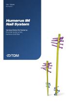
Nail System Various Choice for Humerus Proximal Humerus Nail, Humerus shaft Nail
Open the catalog to page 1
Surgical Technique Ordering Information Part I. Ordering Information Part II.
Open the catalog to page 2
It has already been more than a decade since the company was founded to become a leading company for fracture treatment. While keeping the basics, all employees have worked together and have been quick to reflect customers’ needs. The constant dedication and efforts of physicians for patients always present us with new challenges. TDM knows that these challenges are none other than the minds of doctors for patients. To know this, we wanted to reflect customer requests into our products and services as much as possible, and we will continue to do so in the future. Basic Plus One That ONE for the...
Open the catalog to page 3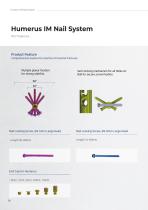
Humerus IM Nail System Comprehensive System for solution of humeral fractures. Multiple planar fixation semi locking mechanism for all Holes on for strong stability. Nail f0r secure screw fixation. Nail Locking Screw, 04.5mm Large Head Nail Locking Screw, 04.0mm Large Head
Open the catalog to page 5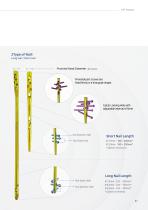
2Type of Naill Long nail / Short nail ore Dynamic Hole Short Nail Length Two Static Hole 0 7.5mm-160-200mm*
Open the catalog to page 6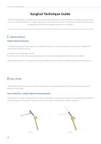
Humerus IM Nail System Surgical Technique Guide TDM as the manufacturer of this device, does not practice medicine and does not recommend this or any other surgical technique for use on a specific patient. The surgeon who performs any implant procedure is responsible for determining and using the appropriate techniques for implanting the device in each patient. The patient may be placed either supine or in a beach chair position so that fluoroscopy can be used to allow intraoperative assessments of fracture reduction. It is approached in anterolateral direction. A 3-5cm incision is made at the...
Open the catalog to page 7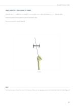
Surgical Technique Guide Using the Guide Pin Holder, insert the Guide Pin at the proper insertion point and advance it in the medullary canal. Check the position of the Guide Pin in both AP and lateral views. Remove the Guide Pin Holder. (figure3) The Proper position of Guide Pin wire in the Protection Sleeve can be adjusted using the Drill Guide (Multi Hole Drill Guide) (Figure 2).
Open the catalog to page 8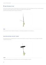
Humerus IM Nail System After insertion Guide Pin, remove the Drill Guide from the Protection Sleeve. Pass the Start Reamer over the pre-inserted Guide pin through the Protection Sleeve to the bone. Reaming to the depth of the medullary canal. Remove the Start Reamer, Protection Sleeve, and Guide Pin. Since the reamer's shaft is twisted in one direction, it must always be operated in the same direction. Alternatively, pass the Cannulated Awl with T-Handle over the Guide Pin to the bone. Advance the awl to the depth of medullary canal with twisting motion. Take care not to plunge to the awl into...
Open the catalog to page 9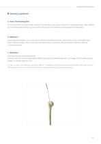
Surgical Technique Guide For insertion of the Long Flumeral Nail, reaming of the medullary canal may be necessary. For reamed techniques, After reduction, push the Reaming Rod, and Ball Tip using Guide Pin Holder down the medullary canal and place the Reaming Rod. Using image intensification, ensure that fracture reduction has been maintained. Starting with the Start Reamer(07.Omm), ream to diameter at least 1,0mm greater than the Nail diameter in accordance with the surgeon's preference. Reaming in 0.5mm increments. After reaming, remove reaming assembly. Insert the Alignment Tube over Reaming...
Open the catalog to page 10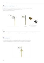
Humerus IM Nail System Assemble Handle is oriented laterally and match the geometry of the Assemble Handle to the Nail. Pass the Assemble Bolt through the Assemble Handle into Nail. Secure the assembly with the Wrench. Each of the three location is a different Size. Before starting Nail insertion, assemble Proximal Target Device to the Assemble Handle, as shown in Figure 4. Insert and advance the Nail into the medullary canal and Assemble Handle is oriented laterally. Check the nail passage across the fracture and control it in two planes to avoid misalignment.
Open the catalog to page 11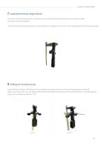
Surgical Technique Guide Ensuring that Proximal Target Device is oriented correctly. Attach the Proximal Target Device to Assemble Handle and tighten the Connecting Bolt. The Humerus Nail end should be at least 2 to 3mm below the cartilage to minimize the risk of impingement while maximizing stability. 8. Drilling for Proximal Screw Insert a Protection Sleeve, Drill Sleeve and Trocar through the most proximal hole of Proximal Targeting Device, (figure 5) After remove Trocar and insert the calibrated Drill Bit and drill carefully until the level of the subchondral bone is reached, (figure 6) Check...
Open the catalog to page 12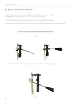
Humerus IM Nail System Read the required length of the screw directly off the calibrated Drill Bit at the back of the Drill Sleeve. Press the Drill Sleeve firmly to the cortex to ensure accurate measurement, (figure 7) Or, alternatively, the Depth Gauge for Nail Locking Screw can be used for screw length determination. And then the 4.5mm Interlocking Screw of selected length is inserted through protection sleeve in the Proximal Target Device. Additionally, the stability can be increased by inserting a screw in to the Calca Locking Hole, (figure 8)
Open the catalog to page 13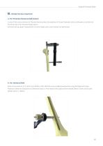
Surgical Technique Guide In case of the screw insertion for Proximal Humerus Nail, the assembly of Trocar, Protection Sleeve, Drill Guide is inserted into the distal hole of the Proximal Target Device. And then drilling, depth measurement of screw length, and screw insertion are performed. Distal screw insertion on (7, 8mm dia x 220mm, 220, 240mm) Humerus Nail should be done using freehand technique. Protection Sleeve for Distal and Drill Sleeve for Distal or Free Handle Drill Guide and Free Handle Sleeve 3.5mm can be used Drill Bit 3.5mm x 160mm.
Open the catalog to page 14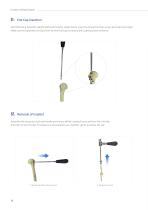
Humerus IM Nail System After Removing Assemble Handle Shaft and Proximal Target Device, insert the proper End Cap using a End Cap Driver, Rigid. Make sure the tightened End Cap Driver tip with End Cap by rotating the Coupling Screw clockwise. 12. Removal of Implant Assemble the extraction shaft and handle and remove all Nail Locking Screws, 04.5mm from the Nail. And then remove the Nail. If resistance is encountered, use a hammer gently to extract the nail.
Open the catalog to page 15All TDM catalogs and technical brochures
 VA Snowman
8 Pages
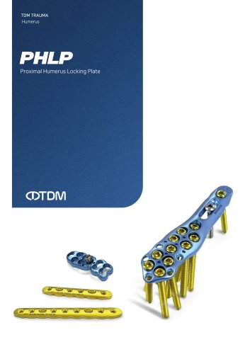 PHLP
PHLP20 Pages
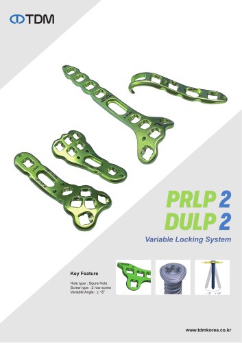 DULP & PRLP
2 Pages
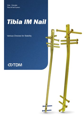 Tibia IM Nail
26 Pages
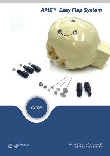 Easy Flap
4 Pages
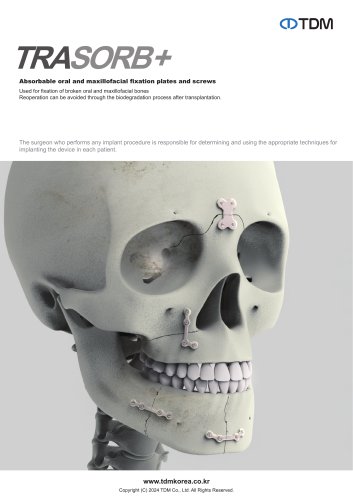 Trasorb+
4 Pages
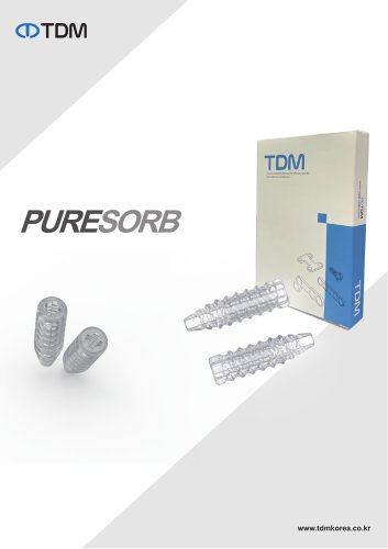 Puresorb
2 Pages
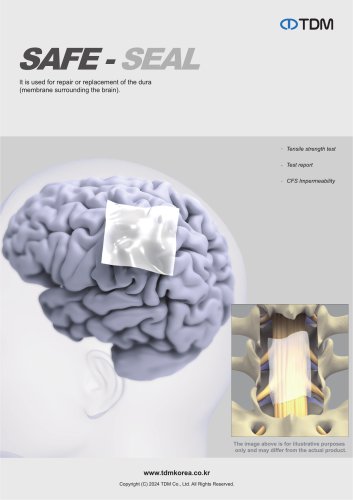 Safe-seal
2 Pages
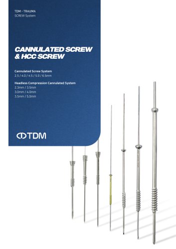 Cannulated & HCC Screws
24 Pages
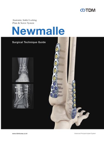 NewMalle
28 Pages
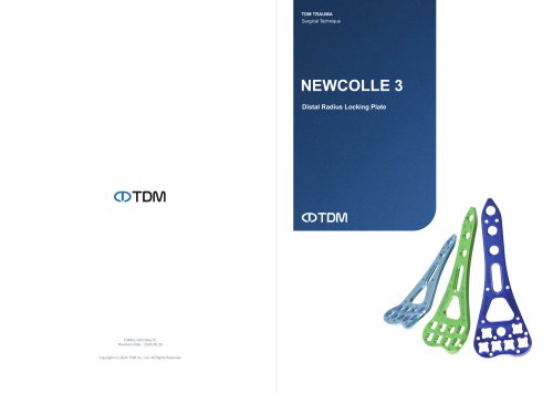 NewColle v3
8 Pages
 Product Overview
47 Pages
- Bone plate
- Compression plate
- Metallic compression plate
- Locking compression plate
- Titanium compression plate
- Distal compression plate
- Compression bone screw
- Metallic compression bone screw
- Proximal compression plate
- Bone substitute
- Forearm compression plate
- Arthrodesis nail
- Medial compression plate
- Lateral compression plate
- Tibia compression plate
- General purpose compression bone screw
- Humerus compression plate
- Metallic intramedullary nail
- Radius compression plate
- External fixation system