Tibia IM Nail
1 /26Pages
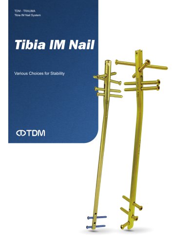
Tibia IM Nail
1 /26Pages
Catalog excerpts
201,3ungang innotceh B/D, 148, Sagimakgol-ro, 3ungwon-gu, Seongnam-si Gyeonggi-do, Korea Tel. 82-31-732-0631 Fax. 82-31-732-0632 69, Cheomdan venture so-ro 37beon-giI, Buk-gu, Gwangju, Korea Tel. 82-62-971-7460 Fax. 82-62-971-7461 Q www.youtube.com/tdmkorea/ fsl www.instagram.com/tdmcoltd/ www.linkedin.com/company/tdmkr
Open the catalog to page 2
Specifications: Nail Surgical Technique Ordering Information
Open the catalog to page 3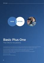
It has already been more than a decade since the company was founded to become a leading company for fracture treatment. While keeping the basics, all employees have worked together and have been quick to reflect customers’ needs. The constant dedication and efforts of physicians for patients always present us with new challenges. TDM knows that these challenges are none other than the minds of doctors for patients. To know this, we wanted to reflect customer requests into our products and services as much as possible, and we will continue to do so in the future. Basic Plus One That ONE for the...
Open the catalog to page 4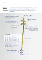
The Tibia Nail System is used for the fractures of the proximal and distal third of the Tibia, including the shaft, stable and unstable fractures, non unions, for the prophylactic nailing of impendingpathological fractures. All implants are Titanium alloy for improved mechanical and fatigue properties. This system offers various “Screw Locking Options”, It can be decided by the surgeon on fracture type. Option size Option size Option size Option size Option size Option size Additional Oblique Locking Advanced Locking Mechanism for anti-rotation Controlled Dynamization Locking Hole Length 26~50mm...
Open the catalog to page 6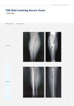
Tibia IM Nail Locking Screw Case
Open the catalog to page 7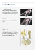
Surgical Technique Position the Patient supine on a radiolucent table with unaffected limb extended away from the affected limb. Optionally, a fracture table may be used with a pin inserted through the calcaneous to place the leg in traction. Flex the affected limb 80-90° and check for the length and rotation by comparison to the unaffected limb. (Figure 1) Make a 2cm incision in line with the intramedullary canal. The patellar tendon may be retracted laterally or medially. (Figure 2) The medullary canal is opened through a superolateral plateau entry portal. The center point of the portal is...
Open the catalog to page 8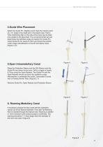
Tibia IM Nail Locking Screw Case Attach the Guide Pin. Slightly punch mark the incision point at a 10° angle to the shaft axis in the lateral view. Hold a Tibia interlocking Nail on the side of the lower leg its distal end parallel to the tibia shaft. The curved proximal nail end determines the definitive angle of insertion for Guide Pin. Insert Guide Pin for nearly 8-10cm and check the position under image intensification in the AP and lateral views. (Figure 4, 5) Place the Protection Sleeve and the Drill Sleeve over the Guide Pin and down to the bone. Drill to a depth of nearly 8-10cm using...
Open the catalog to page 9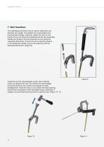
Surgical Technique 7. Nail Insertion The Nail Measuring Plate may be used to determine nail diameter and length. The seleted nail is assembled onto the Assemble Handle; anteriorly, match the notch on the handle to the nail. Place the Assemble bolt into the Assemble Handle and thread it into the proximal nail end using the Assemble Bolt Driver. Ensure the nail is oriented porperly on the Assemble Handle, secure the assembly with the Assemble Bolt Driver. (Figure 9) Insert the nail into intramedullary canal. Use a twisting motion to advance the nail. The monitor the nail passage across the fracture,...
Open the catalog to page 10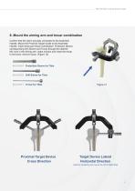
Tibia IM Nail Locking Screw Case Confirm that the nail is securely connected to the Assemble Handle. Mount the Proximal Target Guide to the Assemble Handle. Insert three-part trocar combination. Protection Sleeve, corresponding Drill Sleeve and Trocar through the desired M/L hole in the aiming arm, make incision and insert the trocar to the bone, remove trocar. (Figure 12) 910-01101P Protection Sleeve for Tibia 910-01101D Drill Sleeve for Tibia Proximal Target Device Cross Direction 11
Open the catalog to page 11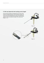
Surgical Technique Ensure that the Drill Sleeve is pressed firmly to the near cortex. Using the corresponding drill bit. Drill through both cortices until the tip of the drill bit penetrates the far cortex. After drilling both cortices, remove the drill bit and the drill sleeve. Insert the depth gauge and check and decide the length of the locking screw. (Figure 13, 14)
Open the catalog to page 12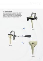
Tibia IM Nail Locking Screw Case Insert the appropriate locking screw through the protection sleeve using screw driver. Ensure locking screw length under image intensification. The tip of the locking screw should not project more than 1-2mm beyound the far cortex. Depending on fracture type and surgeon’s decision, the screw insertion option can be decided and inserted.
Open the catalog to page 13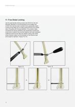
Surgical Technique Use the appropriate locking screws and drill bit for the nail diameter selected it is recommended to lock distally first. Confirm the nail has been inserted to the appropriate depth. Locking of the tibial nail is usually performed from the medial side, if possible with the leg extended. This position helps counteract the forces exerted by the quadriceps muscle that would tend to deform the proximal fragment and also facilitates rotational control of the tibia axis before locking. Also distal screw insertion option can be decided on the fracture type and surgeon’s decision....
Open the catalog to page 14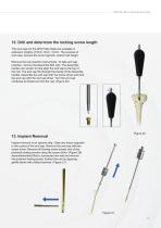
Tibia IM Nail Locking Screw Case 12. Drill and determine the locking screw length The end caps for the APIS Tibia Nails are available in extension lengths of Omm, 5mm, 10mm. The purpose of end caps; prevent the bone ingrowth, extend nail height. Remove the nail insertion instruments. To help end cap insertion, remove the Assemble Bolt only. The Assemble handle can remain to help align the end cap to the top of the nail. The end cap fits through the barrel of the Assemble handle. Assemble the end cap with the screw driver and lock the end cap with the end cap driver. Turn the end cap clockwise...
Open the catalog to page 15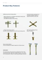
Additional proximal locking options Advanced locking mechanism for increased rotational stability at - Static locking and a controlled dynamization locking hole distal proximal M/L screw hole - Standard M/L screw locking and additional oblique screw locking Self retaining Endcap Driver Ease of Insertion - Distal screw locking options (Two M/L screw locking hole, One A/P screw locking hole) Screw locking Options (It can be decided by surgeon depends on fracture type.) For the fractures of the proximal and distal third of the Tibia, including the shaft, stable and unstable fractures, non-unions,...
Open the catalog to page 16All TDM catalogs and technical brochures
 VA Snowman
8 Pages
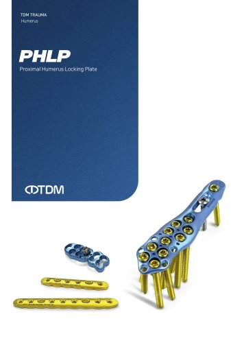 PHLP
PHLP20 Pages
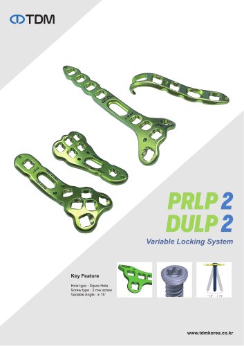 DULP & PRLP
2 Pages
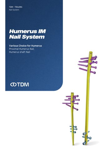 Humerus IM Nail
24 Pages
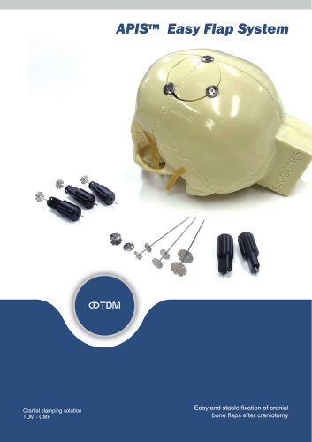 Easy Flap
4 Pages
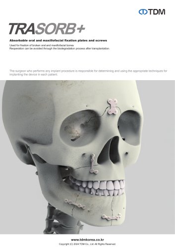 Trasorb+
4 Pages
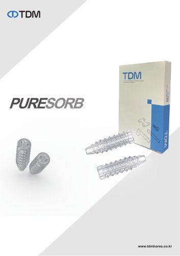 Puresorb
2 Pages
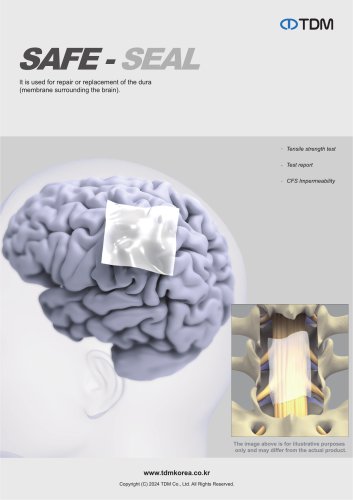 Safe-seal
2 Pages
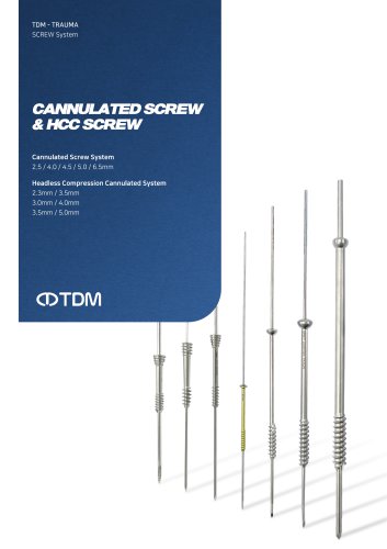 Cannulated & HCC Screws
24 Pages
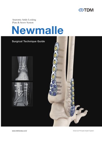 NewMalle
28 Pages
 NewColle v3
8 Pages
 Product Overview
47 Pages
- Bone plate
- Compression plate
- Metallic compression plate
- Locking compression plate
- Titanium compression plate
- Distal compression plate
- Compression bone screw
- Metallic compression bone screw
- Proximal compression plate
- Bone substitute
- Forearm compression plate
- Arthrodesis nail
- Medial compression plate
- Lateral compression plate
- Tibia compression plate
- General purpose compression bone screw
- Humerus compression plate
- Metallic intramedullary nail
- Radius compression plate
- External fixation system