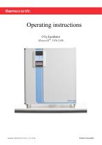
Overview: The Heracell 150i/240i CO2 Incubator by Thermo Scientific is designed for precise environmental control in laboratory settings. This document provides comprehensive operating instructions, including safety guidelines, installation procedures, and maintenance requirements.
General Notes: Emphasizes the importance of adhering to safety protocols and understanding the device's intended use. The manual is crucial for safe operation and maintenance.
Device Delivery: Details on packaging, acceptance inspection, and standard versus optional equipment components for both Heracell 150i and 240i models are provided.
Installation: Instructions cover ambient conditions, room ventilation, space requirements, and transport. Specific guidelines for stacking and retrofitting are included.
Device Description: Includes detailed descriptions of the front and rear views of both models, safety devices, workspace atmosphere, and sensor systems.
Start-up Procedures: Steps for adapting the device to ambient conditions, preparing the workspace, and installing various components are outlined. Instructions for gas and power supply connections are also included.
Operation: Guidelines for preparing and starting the device, including handling interruptions, are detailed. The iCanTM touchscreen controller's operation is explained, with settings for temperature, CO2, and O2 levels.
Shut-down and Maintenance: Procedures for shutting down the device, cleaning, disinfection, and maintenance checks are provided. Calibration procedures for temperature and CO2, as well as instructions for replacing components, are included.
Technical Data and Communication: Technical specifications for both models are listed. Data communication interfaces and command sequences are explained, along with error memory and data logger structures.
Regulatory Compliance and Safety Guidelines: Outlines compliance with German regulations and emphasizes adherence to safety data sheets for gases like CO2, O2, and N2. Stresses the importance of following national regulations in other countries.
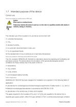
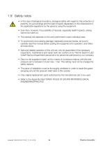
Safety Notes: Biological incubators require strict adherence to safety regulations to protect users and surroundings. Hazards, especially health risks, cannot be entirely eliminated. Safe operation depends on regular inspections and maintenance by authorized personnel. Gas supply must be regulated, and installation areas must be well-ventilated.
Gas Safety: CO2 is harmful and requires specific safety measures during operation. O2 can explode when in contact with grease, and N2 can cause suffocation by reducing oxygen levels. Personnel must be trained in handling these gases and emergency procedures.
Operational Safety Rules: Users must observe weight limits and ensure even sample distribution. Regular checks on door seals and avoiding hazardous substances are crucial. Fire and suffocation hazards are highlighted, with specific instructions for handling oxygen and nitrogen.
Delivery and Packaging: The Heracell 150i/240i incubators are delivered in recyclable packaging. Upon delivery, inspect for completeness and damage. Protective measures are advised for handling sharp edges.
Standard and Optional Equipment: Lists standard and optional components for Heracell 150i and 240i models, including shelves, connectors, and gas hose sets.
Installation Guidelines: Installation requires specific ambient conditions, including a draft-free, dry location with proper ventilation. The device must be placed on a stable, fire-proof surface, and power supply conditions must be met. Avoid placing the incubator directly on the floor to prevent contamination.
Room Ventilation: Proper room ventilation is necessary to handle gas emissions and heat dissipation. Additional ventilation may be required for multiple devices.
Space Requirements: Ensure accessibility for maintenance and avoid obstructing ventilation. Use a floor stand to prevent contamination.
Transport Instructions: Lift the device using designated lift points to avoid injury and damage. Personal Protection Equipment is recommended during transport.
Installation of the Device: HERACELL® 150i/240i can be stacked up to two devices. For the 240i model, an adapter plate is used for thermal separation. Devices are secured by their weight, and stacked devices should not be transported.
Intermediate Storage: The oven can be stored for up to four weeks at temperatures between 20°C to 60°C and humidity below 90%.
Retrofitting/Modifications: Various components can be retrofitted, including gas-tight screens, door hinges, and sensors. Modifications should be performed by authorized technical service.
Description of the Device: Detailed descriptions of components such as stacking elements, glass doors, sensors, and gas connections are provided for both HERACELL® 150i and 240i models.
Safety Devices: Includes door switches, gas detectors, thermal protection, pressure compensation, and alarm systems.
Work Space Atmosphere: Simulates conditions for cell and tissue cultures with controlled temperature, humidity, CO2, and optional O2 levels. Specific water quality is required for humidity control.
Gas Supply: CO2 and O2/N2 supplies are detailed, with specific purity requirements for CO2 and optional configurations for O2 and N2.
Operational Notes: Use sterilized distilled water with specific conductivity and pH levels to avoid damage and voiding warranties. Avoid chloride-containing disinfectants; use mild soap and alcohol for cleaning. Relative humidity is maintained at approximately 93%, with options to lower it to prevent dew formation. Door switch interrupts gas supply and heating when the door is opened, with alarms for prolonged openings.
Device Overview: Describes the HERACELL® 150i and 240i incubators, focusing on their components and functionalities. These devices are equipped with sensors for monitoring CO2 and optional O2 levels, which are integral to the control system that manages heating and gas supply. The blower ensures even temperature distribution, and thermal protection prevents overheating by reducing temperature if it exceeds set limits.
Supply Interface: The supply interface at the rear of the device includes connections for gas supply, power, and communication interfaces (RS 232 and optional USB). The gas supply must be maintained at a fixed pressure, and gases pass through a HEPA filter before entering the workspace. An alarm contact is available for external alarm systems.
Workspace Components: The workspace is designed to minimize contamination and facilitate cleaning. It is made of stainless steel, with optional copper components for enhanced antimicrobial properties. The workspace includes a water reservoir with a sensor to monitor water levels and optional gas humidification for O2 control.
Heating System: The incubator uses an air jacket heating system to prevent condensation and maintain visibility through the glass door. The rear panel includes openings for pressure compensation and access ports for cables and sensors.
Shelf System: The shelf system is adjustable and designed to prevent tilting. It is important to adhere to weight limits to avoid damage. The document provides instructions for installing and removing support rails and shelves.
Optional Features: The HERACELL® 240i can be equipped with a bottle turning device for rotating samples. The device's modular layout allows for flexible operation of these devices.
Start-up Procedures: Before initial use, the incubator must be decontaminated, and workspace components cleaned. The device should adapt to ambient conditions before start-up. Installation of the shelf system does not require tools, and leveling the device is necessary for proper operation.
Installation and Start-up Procedures for Heracell 150i/240i: Gas humidification system is installed parallel to the rear panel of the device. Connect the hose to the gas humidification sleeve and the device's oxygen or nitrogen supply line. Ensure the humidification system is aligned with the rear panel.
Bottle Turning Devices Installation: Align the roller insert with the workspace opening and slide it onto the shelf supports. Insert the drive roller and connect the cable to the control unit. Position idle rollers according to bottle diameter and set the rotation speed based on bottle diameter and drive roller set value.
Center Strut Installation: For devices with a 6-segment insert, install two center struts with perforations. Insert the upper guide into the ceiling receptacle and the lower guide into the floor hole, stabilizing with spring pressure.
Gas Connection: Ensure gas purity of at least 99.5% and maintain operating pressure between 0.8 and 1.0 bar. Connect gas pressure hoses to the gas supply system and sterile filter. For devices without gas monitoring, ensure pressure compensation openings are not obstructed.
Power Supply Connection: Connect the device to a grounded power supply with correct voltage and current ratings. Ensure the power cord is routed safely and the power socket remains accessible for emergency disconnection.
RS-232 and USB Interface Connections: Use a standard RS-232 cable for data communication. For USB connections, ensure compatibility with USB 1.1 and 2.0 standards and install necessary drivers.
Alarm Contact Connection: Connect the alarm system using the provided connector and ensure compatibility with the alarm relay specifications. Route the alarm cable safely to avoid hot surfaces.
Operation Preparation: Before starting operation, apply necessary protective equipment and remove jewelry.
Device Check and Preparation: Before starting the operation of the Heracell 150i/240i incubator, ensure all device components are functioning correctly. This includes checking gas hoses, access ports, pressure compensation openings, glass door seals, and shelf systems. Optional components like gas humidification and bottle turning devices should be properly connected and aligned. The workspace must be disinfected according to hygiene guidelines, avoiding explosive disinfectants.
Starting Operation: Fill the water tray with processed water, ensuring it does not exceed the upper level mark. Open the CO2/O2/N2 supply system valves. Turn on the device using the power switch. Set temperature and CO2/O2 levels on the operating panel. Start the contra-con decontamination routine. Use the auto-start routine to begin device operation, which adjusts temperature and humidity and calibrates the CO2/O2 system.
Loading the Device: Load cultures or bottles onto the device, ensuring not to exceed 70% of the workspace to maintain air circulation and heat distribution. Avoid explosive substances and ensure the ambient air is free of solvents.
Interruption of Operation: To prevent contamination during operation interruptions, remove all samples and tools, clean and disinfect the internal space, and decontaminate the device.
Handling and Control: The iCanTM touchscreen controller allows for easy operation with a power switch and pressure-sensitive areas for temperature, CO2, and O2 displays. The device can be operated with or without O2/N2 control, and settings can be adjusted via the touchscreen.
Factory Presettings and Heat-up Phase: The device comes with preset values for temperature (37°C), CO2 (0.0%), and optional O2 (21.0%). Upon startup, the control loop sensors undergo a heat-up phase before displaying actual values.
Auto-start Routine: This routine automates the start and adjustment of the CO2 measuring system, ensuring accurate operation. It should be used when significant changes are made to settings or after extended operation interruptions.
Auto-Start Routine: The auto-start routine for the device can take up to 10 hours to complete, especially in cold conditions. It requires the CO2 and O2 set values to be predetermined and the workspace atmosphere to consist of ambient air. The floorpan must be filled with water. The routine is interrupted if the glass door is opened or the power supply is interrupted, and it will restart once conditions are restored.
Conditions Preventing Auto-Start: The routine cannot start if there are issues with the temperature control loop, such as sensor breakage, excessive deviation from set values, or communication failures. Similarly, issues with the CO2 gas supply control loop can prevent the start.
Activating Auto-Start: To activate, ensure gas supply valves are open, fill the floorpan with water, and set temperature, CO2, and O2 values on the touchscreen. The routine can be canceled or resumed using the touchscreen controls.
User Configuration: The user configuration menu allows adjustments to settings, event logging, options, icon descriptions, keypad lock, and software versions. Key settings include keypad lock coding, date/time, contrast, key tone, interface baud rate, display language, and reminder intervals.
Event Logging: The device logs events and errors, displaying them in chronological order. The logging cycle time can be adjusted, affecting how long entries are retained. Errors are listed with details such as control loop, date, time, and description.
Options: The document mentions options for further customization and control, though details are not fully provided in the excerpt.
Options Overview: The document outlines the settings for various functional device options including alarm relay, low humidity, gas-tight screen, water level sensor, audible alarm, bottle turning device (optional), and CO2 (optional).
Alarm Relay Setting: The alarm relay connects the device's monitoring system to an external system. Network monitoring can be enabled or disabled, detecting power failures as errors. The relay cannot be turned off.
Low Humidity Setting: To prevent condensation, the humidity can be lowered from 93% to 90%. This requires a permanent setting and an extended adaptation phase.
Gas-Tight Screen Setting: Devices with a gas-tight screen have shorter recovery times for incubation parameters. The control system must be adjusted accordingly.
Water Level Sensor: The sensor can be turned off to prevent alarms during operations with ambient humidity or dry auto-start routines.
Audible Alarm: The audible alarm can be disabled, though it sounds when errors are detected alongside visual messages and alarm relay activation.
Bottle Turning Device Speed: Available only on HERACELL® 240i, the speed of drive rollers can be set from 0% to 100%. The device icon appears in the main menu if configured.
O2 Control: O2 control can be toggled on/off depending on work process requirements. The O2 display shows actual values only when the control is active.
Icon Descriptions: Icons in the main menu indicate operating states or errors, such as low humidity, keypad lock, overtemperature, and gas cylinder status.
Gas Cylinder Monitoring: Optional gas monitoring displays cylinder levels. Manual or automatic changeover occurs when pressure drops below 0.6 bar.
Keypad Lock: The keypad lock can be enabled/disabled with a code. If forgotten, it must be reset by technical support.
Software Versions: The menu displays unit software versions.
Trend Display Scaling: The trend display for temperature, CO2, and O2 can be scaled and zoomed for detailed analysis.
Error Messages: The system monitors control loops and sensors, issuing alarms and messages for detected errors. Errors are logged in the event display.
Response to Error Messages: Errors due to user actions can be reset by accepting the message. Technical defects keep the alarm active until resolved.
Overtemperature Protection: If activated, the device switches to emergency control. The error must be acknowledged and the device cooled before resetting.
Handling and Control (iCanTM Touchscreen Controller): Provides an error table indicating the source, cause, and possible corrections for errors. It advises contacting technical support if issues persist after troubleshooting.
Error Messages: Common errors include communication failures, sensor breakages, and calibration issues. Most require contacting service, while some can be resolved by resetting the device.
Shut-down Procedures: Steps include removing culture containers, draining water, performing decontamination, and disconnecting power and gas supplies. Continuous ventilation is required until the device is fully shut down.
Cleaning and Disinfection: Use water and detergent for exterior surfaces and a dry microfiber cloth for the display. Avoid solvents that can damage plastic components.
Decontamination: The contra-con routine is an automated cycle for decontaminating the workspace. Manual wipe/spray disinfection involves pre-disinfection, cleaning, and final disinfection stages.
Safety Precautions: Use protective gear to avoid health hazards from contaminated surfaces and disinfectants. Ensure the device is de-energized before cleaning.
Contra-con Decontamination Routine: The routine takes approximately 25 hours, creating a hot and humid atmosphere for effective decontamination. It cannot start if certain failures are present, such as sensor issues or gas supply problems. After completion, the device must be restarted using the auto-start routine.
Contra-Con Decontamination Routine: The contra-con decontamination routine is a critical process for maintaining the cleanliness of the Heracell 150i/240i incubators. It involves five phases: heating, decontamination, condensation, cool-down, and drying. The workspace is heated to 90°C, and the entire process takes approximately 71 hours. This routine should be performed every three months to ensure optimal operation.
Activating and Interrupting Contra-Con: To activate the contra-con routine, press the CONTRA-CON key and follow the instructions to remove samples and accessories, pump out water, and fill the floorpan with processed water. The routine can be interrupted or canceled using the STOP and END keys, respectively. If an error occurs, the routine automatically switches to the cool-down phase.
Maintenance and Inspections: Regular maintenance is essential for the operability and safety of the device. Daily checks include gas supply systems, while annual inspections cover door seals, pressure openings, and electrical safety. Service intervals include a three-month auto-start and decontamination routine, and an annual gas inlet filter replacement.
Temperature and CO2 Calibration: Temperature calibration involves setting the device to a specific temperature and using a calibrated instrument to measure and adjust the control settings. CO2 calibration requires a similar process, using a portable IR readout instrument to ensure accurate CO2 levels. Both calibrations should be performed every three months.
Equipment Log Book and Returns: Maintaining an equipment log book is recommended for recording inspections, tests, and maintenance activities. For repairs, contact customer service for a Return Materials Authorization (RMA) number before returning any materials.
Safety and Precautions: Only authorized personnel should perform work on electrical components, and all safety devices must be reinstalled and checked after inspections. Proper decontamination is mandatory before returning any potentially contaminated equipment.
Maintenance Procedures: Gas Inlet Filter Replacement: Ensure the plastic thread is not canted when installing the new filter. Secure the gas hose with a clamp. Device Fuse Replacement: Use time delay fuses, 6.3 A (5x20 mm). Remove the fuse holder by squeezing locking tabs, replace the faulty fuse, and reinsert the holder. Door Seal Replacement: No tools required. Remove the old seal and press the new seal into the retaining slot, ensuring it is flush with the door frame.
Disposal Instructions: All components must be decontaminated before disposal. Attach a declaration of non-objection detailing decontamination measures. Thermo Fisher Scientific offers a recycling service at the owner's expense.
Technical Data: HERACELL® 150i: Chamber volume approx. 151 liters, temperature control range RT +3...55°C, CO2 gas purity min. 99.5%, rated voltage options 230V, 120V, 100V. HERACELL® 240i: Chamber volume approx. 238 liters, similar temperature and gas specifications as 150i, with slight variations in dimensions and weight.
Data Communication: Interfaces: RS 232 and optional USB port for data communication. USB operates as a virtual COM port. Command Sequences: Data exchange uses ASCII characters. Protocols for reading and writing parameters are defined with specific command structures.
Data Communication Overview: Provides detailed technical specifications and procedures for data communication in the Heracell 150i/240i devices. It includes information on error memory structure, data logger functionality, and communication protocols.
Error Memory Structure: The error memory can store up to 22 error messages, with queries returning 11 data sets. Each data set is encrypted into 21 ASCII characters and includes information such as date, time, device status, and error messages. The document provides examples of error messages in both hexadecimal and bit coding formats.
Data Logger Functionality: The data logger can store up to 10,000 events, capturing user actions, system events, and error messages. It records data from control loops for temperature, CO2, and O2. The logger can be queried to retrieve data sets, which are encrypted into ASCII characters. Each data set includes date, time, device status, and specific control loop values.
Communication Protocols: Outlines commands for querying the data logger and error memory, including setting reading pointers and handling communication errors. It also provides code examples for implementing these queries, detailing functions for sending and receiving data, converting values, and writing data to files.
Key Parameters and Codes: Lists various error and event codes, describing their meanings and associated data. It includes specific codes for temperature, CO2, and O2 control loops, as well as general device status and water level errors.
Recommendations and Best Practices: For effective data management, it is recommended to regularly query the data logger and error memory to monitor device status and address any issues promptly. The document emphasizes the importance of understanding the coding structure for accurate data interpretation.
Data Communication Overview: Outlines the data communication protocols for the HERACELL® 150i/240i incubators. It includes procedures for reading and archiving error messages and event entries, creating service files, and setting up communication between the device and a PC.
Specifications: The program supports reading error messages and event entries, storing them in CSV format, and creating service files in SRF format for troubleshooting.
Installation Procedure: Run SETUP.EXE from the PROGRAMS directory on the data CD. Follow the installation steps: confirm the license agreement, installation extent, and restart the computer after installation.
Operating Instructions: The user interface is divided into MAIN and GENERAL menus. MAIN includes firmware version output and program exit. GENERAL includes submenus for setting transmission speed, testing communication, adjusting date and time, reading error messages, and creating service files.
Key Submenus: PRESETTING: Set transmission speed (9,600 to 115,200 baud) and select the serial port. TEST COM: Test communication connection with the incubator. DATE & TIME: Adjust date and time settings. ERROR LOGGER: Read and save error messages. DATA LOGGER: Read and save event entries. SERVICEFILE: Create and save service files for technical support. PASSWORD: Restricted access for service personnel.
Device Log: Includes sections for recording maintenance work, device type, serial number, location, part number, service number, and operator's notes.





 Nunc Cell Factory systems
 CryoStar NX50
 MSC-Advantage BSC
 Multifuge
 Thermo Scientific Pico 17 / 21
 Revco® Blood Bank Refrigerators
 Multidrop Combi nL
 Forma Environmental Chambers
 MaxQ 6000
 Multi Tube Rotator
 picoSpin Spectrometer
 1300 Series A2
 CO2 Incubator Family
 CO2 incubators
 MaxQ Mini 4450 Shaker
 E1-ClipTip Electronic Pipette
 Varioskan™ LUX
 ISQ Series Mass Spectrometers
 Q Exactive™ BioPharma
 Q Exactive Plus
 LTQ XL™
 Platinum DNA polymerases
 -80°C Benchtop Freezer
 Nicolet iS10 FT-IR Spectrometer
 Ion S5 and Ion S5 XL Systems
 SureTect Range
 QuantStudio™ 3
 Furnaces
 Nunc Serological Pipettes
![Vanquish Duo UHPLC System [ZH]](https://img.medicalexpo.com/pdf/repository_me/78678/vanquish-duo-uhplc-system-zh-191145_1mg.jpg) Vanquish Duo UHPLC System [ZH]
Vanquish Duo UHPLC System [ZH] native MS
 Compound Discoverer Software
 Vanquish Horizon UHPLC System
 Thermo Scientific TSQ Duo
 Thermo Scientific TSQ 8000 Evo
 Heraeus Labofuge 300
 Heraeus Cryofuge 5500i
 Heraeus Clinifuge Centrifuge
 Vials and Closures Catalog 2014-2015
 RM 200 EG
 Darwin LIMS
 Immunohistory Solutions
 Process Water Products Catalog
 Technical Training Catalog
 FBS Alternatives
 Pierce Magnetic Beads
 interactive catalog today
 HERAGUARD HPH clean benches
 MBC 240 Bench Top Analyzer
 Konelab 20
 Indiko




![ISQ 7000 Single Quadrupole GC-MS System VPI [ZH]](https://img.medicalexpo.com/pdf/repository_me/78678/isq-7000-single-quadrupole-gc-ms-system-vpi-zh-191148_1mg.jpg)
![ISQ 7000 Single Quadrupole GC-MS System [ZH]](https://img.medicalexpo.com/pdf/repository_me/78678/isq-7000-single-quadrupole-gc-ms-system-zh-191147_1mg.jpg)


![Thermo Scientific Herasafe KS and KSP Class II Biological Safety Cabinets [EN]](https://img.medicalexpo.com/pdf/repository_me/78678/thermo-scientific-herasafe-ks-ksp-class-ii-biological-safety-cabinets-en-85081_1mg.jpg)


 Nunc Cell Factory systems