- Catalogs
- Thermo Scientific
- Model 310 Series Forma Direct Heat CO2 Incubator
Model 310 Series Forma Direct Heat CO2 Incubator
1 /90Pages

Model 310 Series Forma Direct Heat CO2 Incubator
1 /90Pages
Catalog excerpts

Model 310 Series Forma Direct Heat CO2 Incubator Operating and Maintenance Manual 7010310 Rev. 9
Open the catalog to page 1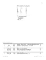
* T/C is a thermal conductivity sensor. IR is an infrared sensor. ** All units are 50/60 Hz. † Copper interior Re-installed “Specs are based on...” on Specification page. Unintentional removal ccs Updated RH low alarm ringback time from 30 to 15 minutes Updated drawer specs - sliding and stationary Replaced 190793 display board with 190609 (color) Updated 310-203-0-D - bezel part number 190786 Updated stacking instructions (screws), pg 1-5 Thermo Scientific
Open the catalog to page 2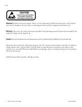
Important Read this instruction manual. Failure to read, understand and follow the instructions in this manual may result in damage to the unit, injury to operating personnel, and poor equipment performance. ▲ Warning If this unit is not used in the manner specified in this operating manual, the protection provided by the equipment design may be impaired. ▲ Caution All internal adjustments and maintenance must be performed by qualified service personnel. ▲ Material in this manual is for information purposes only. The contents and the product it describes are subject to change without notice....
Open the catalog to page 3
Important operating and/or maintenance instructions. Read the accompanying text carefully. Potential electrical hazards. Only qualified persons should perform procedures associated with this symbol. Equipment being maintained or serviced must be turned off and locked off to prevent possible injury. Hot surface(s) present which may cause burns to unprotected skin, or to materials which may be damaged by elevated temperatures. Marking of electrical and electronic equipment, which applies to electrical and electronic equipment falling under the Directive 2002/96/EC (WEEE) and the equipment that...
Open the catalog to page 4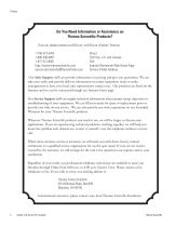
Do You Need Information or Assistance on Thermo Scientific Products? If you do, please contact us 8:00 a.m. to 6:00 p.m. (Eastern Time) at: 1-740-373-4763 1-800-438-4851 1-877-213-8051 http://www.thermoscientific.com [email protected] Direct Toll Free, U.S. and Canada FAX Internet Worldwide Web Home Page Service E-Mail Address Our Sales Support staff can provide information on pricing and give you quotations. We can take your order and provide delivery information on major equipment items or make arrangements to have your local sales representative contact you. Our products...
Open the catalog to page 5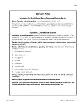
Warranty Notes Information You Should Know Before Requesting Warranty Service • Locate the model and serial numbers. A serial tag is located on the unit itself. • For equipment service or maintenance, or with technical or special application inquiries, contact Technical Services at 1-800-438-4851 or 1-740-373-4763 (USA and Canada). Outside the USA, contact your local distributor. Repairs NOT Covered Under Warranty • Calibration of control parameters. Nominal calibrations are performed at the factory; typically ±1°C for temperature, ±1% for gases, and ±5% for humidity. Our service personnel can...
Open the catalog to page 6
Table of Contents Section 1 Calibration . . . . . . . . . . . . . . . . . . . . . . . . . . . . . . . . . . . . . . . . . . . . . . . . . .2-1 Calibrating the Temperature . . . . . . . . . . . . . . . . . . . . . . . . . . . . . . . .2-1 Calibrating the T/C CO2 System . . . . . . . . . . . . . . . . . . . . . . . . . . . .2-2 Calibrating the Infrared CO2 System . . . . . . . . . . . . . . . . . . . . . . . . .2-3 Calibrating Relative Humidity . . . . . . . . . . . . . . . . . . . . . . . . . . . . . .2-4 Configuration . . . . . . . . . . . . . . . . . . . . . . . . . . . . . . . . . . . . . ....
Open the catalog to page 8
Factory Options . . . . . . . . . . . . . . . . . . . . . . . . . . . . . . . . . . . . . . . . . . . . . .6-1 Connect Remote Alarm Contacts . . . . . . . . . . . . . . . . . . . . . . . . . . . .6-1 Connect RS485 Interface . . . . . . . . . . . . . . . . . . . . . . . . . . . . . . . . .6-2 Connecting the Analog Output Boards . . . . . . . . . . . . . . . . . . . . . . .6-2 CO2 Gas Guard . . . . . . . . . . . . . . . . . . . . . . . . . . . . . . . . . . . . . . . . .6-5 Humidity Readout . . . . . . . . . . . . . . . . . . . . . . . . . . . . . . . . . . . . . . .6-6 Uninterruptible Power Supply...
Open the catalog to page 9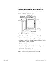
Incubator components are described below. Figure 1-1. Model 310 Series Direct Heat Incubator • Outer Door - Reversible to opposite swing, see Section 5 Inner Door - Reversible to opposite swing, see Section 5 Chamber Gas Sample Port - Used for sampling chamber CO2 content using a FYRITE or similar instrument. Main Power Switch Control Panel - Keypad, Displays and indicators (See Figure 1-2) Leveling Legs - Used to level the unit Note The incubators are stackable. Information follows. ▲ Thermo Scientific
Open the catalog to page 10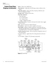
Section 1 Installation and Start-up Control Panel Keys, Displays & Indicators Silence - Silences the audible alarm. Alarm Indicator - Light pulses on/off during an alarm condition in the cabinet. Mode Select Switch - Used to select Run, Setpoints, Calibration and System Configuration Modes. Message Center - Displays system status. Mode Select Indicators Run: Run Menu Set: Set Points Menu Cal: Calibrate Menu Config: Configuration Menu Up and Down Arrows - Increases or decreases the number values, toggles between choices. Enter - Stores the value into computer memory. Heat Indicator - Lights when...
Open the catalog to page 11
Section 1 Installation and Start-up Keypad Operation The Model 310 Series direct heat incubator has four basic modes which allow incubator setup: Run, Setpoints, Calibration and System Configuration. Run is the default mode which the incubator will normally be in during operation. Set is used to enter system setpoints for incubator operation. Calibration is used to calibrate various system parameters. Configuration allows for custom setup of various options. The chart below shows the selections under each of the modes. RUN Default Mode T/C units only IR units only *T/C units only SETPOINT Temperature...
Open the catalog to page 12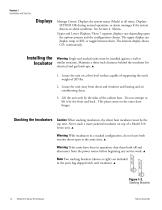
Section 1 Installation and Start-Up Message Center: Displays the system status (Mode) at all times. Displays SYSTEM OK during normal operation, or alarm messages if the system detects an alarm condition. See Section 4, Alarms. Upper and Lower Displays: These 7 segment displays vary depending upon the options present and the configuration chosen. The upper display can display temp or RH, or toggle between them. The bottom display shows CO2 continuously. Warning Single and stacked units must be installed against a wall or similar structure. Maintain a three-inch clearance behind the incubator for...
Open the catalog to page 13All Thermo Scientific catalogs and technical brochures
 CryoStar NX50
2 Pages
 MSC-Advantage BSC
54 Pages
 Multifuge
58 Pages
 Thermo Scientific Pico 17 / 21
52 Pages
 CO2 Incubator HERAcell 150 i / 240 i
196 Pages
 Revco® Blood Bank Refrigerators
37 Pages
 Multidrop Combi nL
4 Pages
 Forma Environmental Chambers
25 Pages
 MaxQ 6000
40 Pages
 Multi Tube Rotator
13 Pages
 picoSpin Spectrometer
6 Pages
 1300 Series A2
76 Pages
 CO2 Incubator Family
28 Pages
 CO2 incubators
7 Pages
 MaxQ Mini 4450 Shaker
40 Pages
 E1-ClipTip Electronic Pipette
108 Pages
 Varioskan™ LUX
54 Pages
 ISQ Series Mass Spectrometers
412 Pages
 Q Exactive™ BioPharma
16 Pages
 Q Exactive Plus
4 Pages
 LTQ XL™
4 Pages
 Platinum DNA polymerases
6 Pages
 -80°C Benchtop Freezer
2 Pages
 Nicolet iS10 FT-IR Spectrometer
12 Pages
 Ion S5 and Ion S5 XL Systems
2 Pages
 SureTect Range
4 Pages
 QuantStudio™ 3
8 Pages
 Furnaces
2 Pages
 Nunc Serological Pipettes
3 Pages
 Nunc Cell Factory systems
8 Pages
![Vanquish Duo UHPLC System [ZH]](https://img.medicalexpo.com/pdf/repository_me/78678/vanquish-duo-uhplc-system-zh-191145_1mg.jpg) Vanquish Duo UHPLC System [ZH]
Vanquish Duo UHPLC System [ZH]12 Pages
 native MS
16 Pages
 Compound Discoverer Software
12 Pages
 Vanquish Horizon UHPLC System
16 Pages
 Thermo Scientific TSQ Duo
9 Pages
 Thermo Scientific TSQ 8000 Evo
16 Pages
 Heraeus Labofuge 300
2 Pages
 Heraeus Cryofuge 5500i
8 Pages
 Heraeus Clinifuge Centrifuge
2 Pages
 Vials and Closures Catalog 2014-2015
128 Pages
 RM 200 EG
4 Pages
 Darwin LIMS
2 Pages
 Immunohistory Solutions
292 Pages
 Process Water Products Catalog
68 Pages
 Technical Training Catalog
15 Pages
 FBS Alternatives
8 Pages
 Pierce Magnetic Beads
16 Pages
 interactive catalog today
222 Pages
 HERAGUARD HPH clean benches
2 Pages
 MBC 240 Bench Top Analyzer
4 Pages
 Konelab 20
2 Pages
 Indiko
6 Pages


![ISQ 7000 Single Quadrupole GC-MS System VPI [ZH]](https://img.medicalexpo.com/pdf/repository_me/78678/isq-7000-single-quadrupole-gc-ms-system-vpi-zh-191148_1mg.jpg)
![ISQ 7000 Single Quadrupole GC-MS System [ZH]](https://img.medicalexpo.com/pdf/repository_me/78678/isq-7000-single-quadrupole-gc-ms-system-zh-191147_1mg.jpg)


![Thermo Scientific Herasafe KS and KSP Class II Biological Safety Cabinets [EN]](https://img.medicalexpo.com/pdf/repository_me/78678/thermo-scientific-herasafe-ks-ksp-class-ii-biological-safety-cabinets-en-85081_1mg.jpg)


- Vertical refrigerator
- Laboratory freezer
- 1-door refrigerator
- Laboratory refrigerator
- Automatic defrost refrigerator
- 1-door freezer
- Electric refrigerator
- Laboratory incubator
- Refrigerator with glass door
- Laboratory centrifuge
- Sample tube
- Laboratory agitator
- Benchtop centrifuge
- Laboratory test tube
- General purpose laboratory shaker
- Sample preparation system
- Blood centrifuge
- Benchtop laboratory agitator
- Automatic sample processor
- Clinical chemistry analyzer